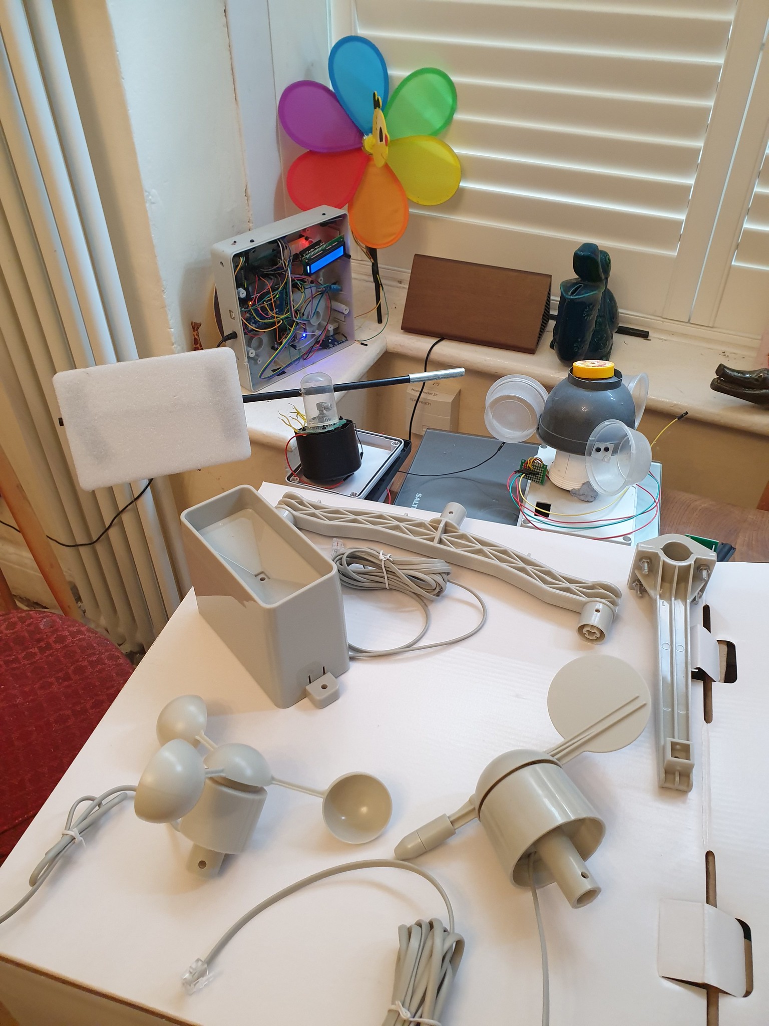
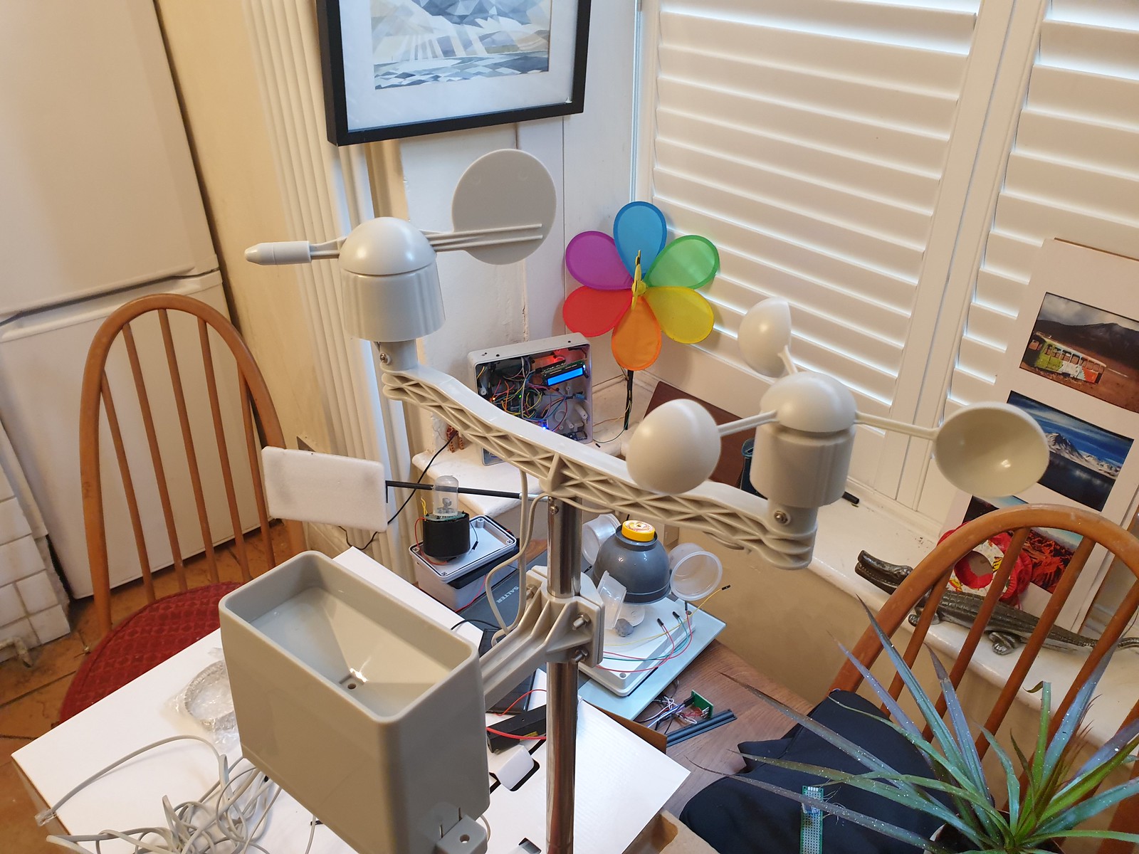
Wind and Rain sensor kit newly arrived from SparkFun Electronics to upgrade an Arduino Weather Station project.
SparkFun Weather Sensor Kit, DIY prototypes, Arduino Weather Station
Also pictured are earlier DIY prototypes – a childrens bee wind spinner with hall effect sensor to count rotations, an anemometer made from recycled plastic packaging utilising a IR Led optical rotary encoder and a wind vane with eight fixed directional magnetic switches.
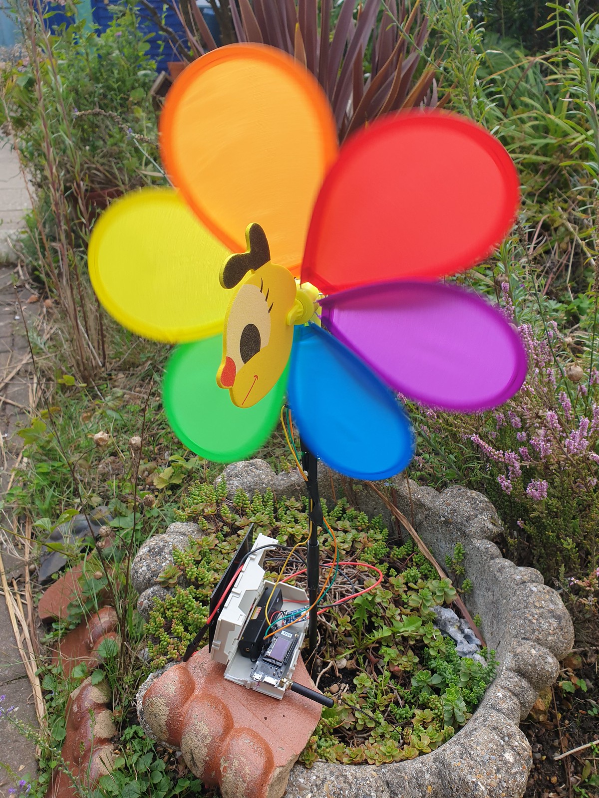
Bee Windmill Anemometer with ESP32 LoRa Transmitter running on single 3.3v Li-Ion cell.
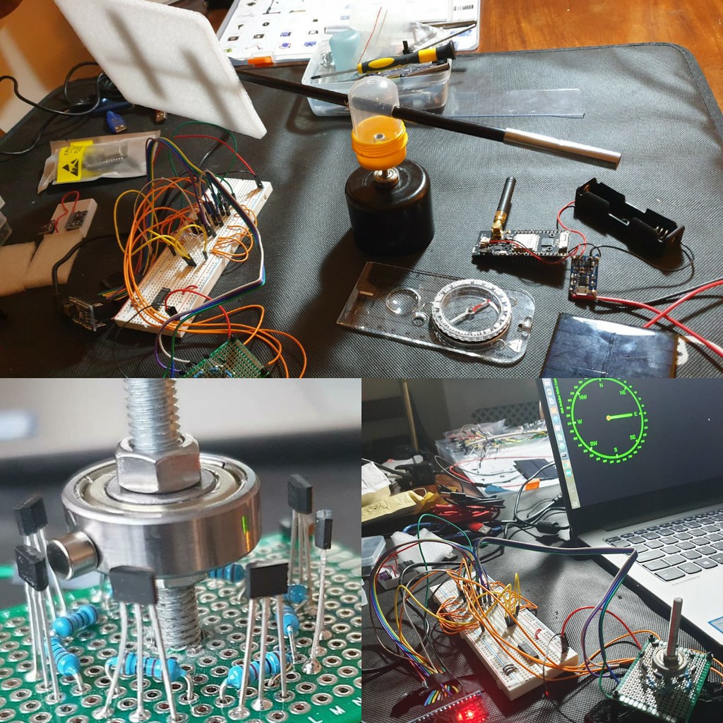
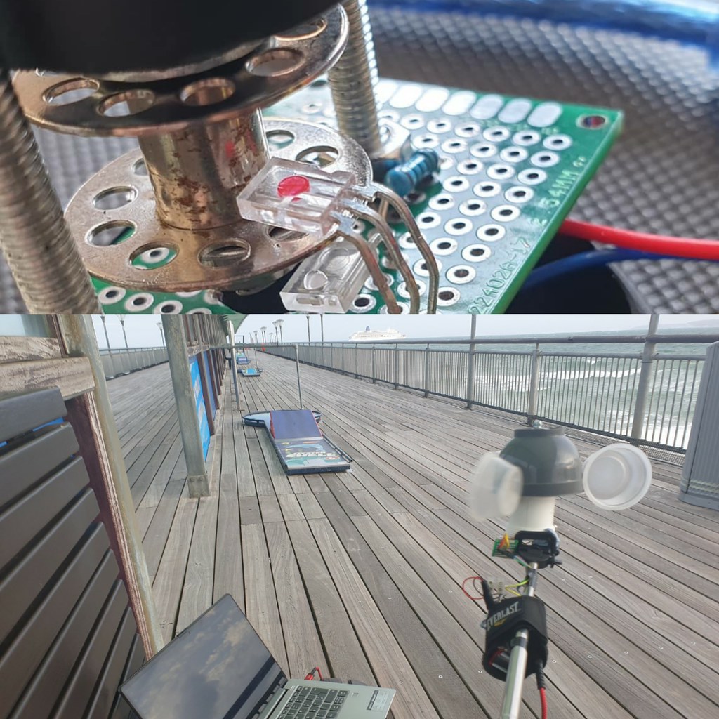
8 Durection WInd Vane with magnetic hall sensor array and WebSocket TCP web browser interface.ESP8266 Anemometer with optical IR Led sensor, wifi connectivity and D3.js websocket provisioned UI.
Weather station projects are a popular accessible introduction to microelectronics; a microcontroller and sensors can be found at low cost, modular hardware design results in easy assembly and open software platforms like Arduino IDE streamline packaging and deployment of code to devices.
Analysing real time or historical time series data, from weather sensors is a lot of fun. Frameworks like R Project for Math Stats: https://www.r-project.org/ ) and Python, Pandas, Numpy & Mathplotlib provide implementations of most alogirithms and convenient data structures for importing & manipulating data.
Techniques and methods are transferable and can be applied to other domains or ontologies – finanicial, accounting data for example.
With advent of 3d modelling & printing it is also feasible for an enthusiast to design and fabricate via a 3d printer custom sensor components, perhaps using template models downloaded from repos like ThingiVerse.
In competition marine OpenWind are defining what smart network connected sensors can achieve utilising Bluetooth LE to make near real time wind data available on smartphone.
Assembled SparkFun Weather Sensor Kit
Ideal for enthusiast or educator SparkFun Weather kit comes wihout circuitry, microcontroller or software. An add-on PCB designed for use with Arduino / ESP32 can be purchased or Datasheet Technical Specs provide reference sensor circuit designs, not significantly complex due to use of magnetic reed switch and variable resistance technology.
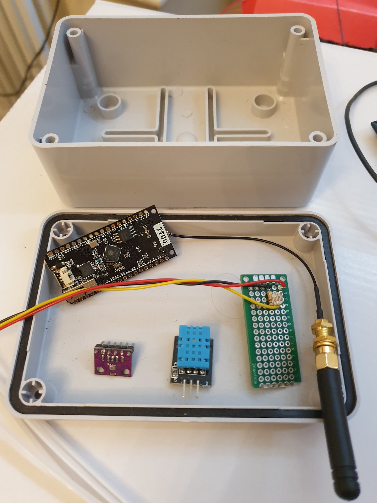
MCU Sensor Control & Relay Unit – IP67 Weather Proof Enclosure, ESP32 TTGO LoRa microcontroller, light, temperature and air pressure sensors.
Traditionally 433MHz RF has been used for base station to transmitter devices. A popular project is to use Arduino, a cheap 433Mhz receiver and a library to read data from a commercial weather station designed for use with manufacturers display, enabling this data to be provisioned to the cloud.
For data transmission non GPRS (cellular) options include Bluetooth LE (range ~100 metres) or LoRa (Long Range Low Power Network – range between 300 – 10km depending on antenae) offering cableless wireless connectivity allowing remote sensor situation with no associated network costs.
At data layer WebSockets and MQTT for IOT devices are challenging serial protocols as defacto lightweight, reliable & easy to implement transport relays.
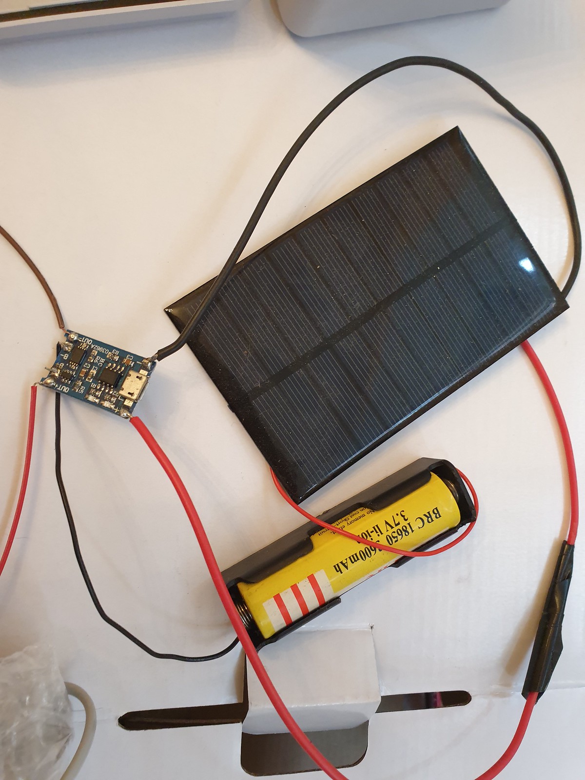
Apart from range and connectivity goals of low power consumption for efficient and long battery running time combined with solar charging enable devices to run standalone for long periods.
Is a single 3.3v Li-Ion Battery Cell Sufficient? TP405 Charging Module & Solar Panel
Weather Stations have applications beyond meteorology in smart agriculture, industrial, safety monitoring and for wind or wave based leisure pursuits.
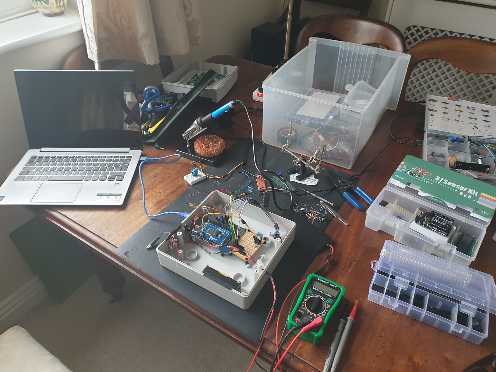
Assembling DIY Arduino Mega Weather Station v1.0
More generally Internet of things wireless networked smart sensor platforms can be used for many purposes and combined with AI and Machine Learning algorithms useful insight and patterns within data can be analysed, classified and predicted.
SparkFun Smart ETextiles & Conductive Thread Kit
Personally, I really enjoyed SparkFun Arduino LilyPad e-textile, smart fabrics and conductive thread kit, so looking forward to now spinning up the Weather Station sensors!
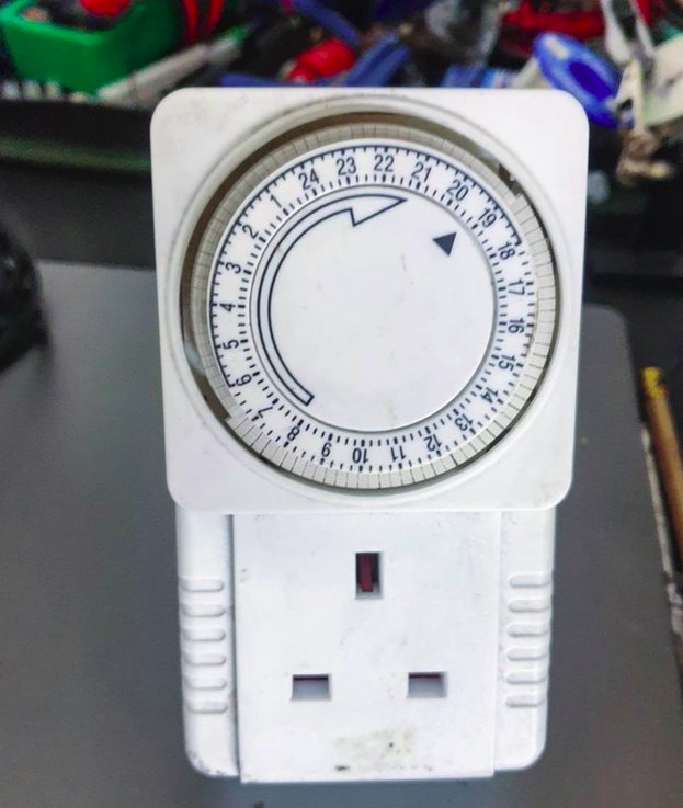
Timed Device is a library for Arduino / ESP 8266/32 embedded platforms written to emulate a simple plug in timer for an electrical device, where pins in a ring are set to define hour/minute status. Designed to be simple and lightweight optimisation is for low memory.
Arduino ATMega328 and related embedded microcontrollers provide internal high precision clock based timers suitable for events with second, millisecond and fine granularity (to clock speed 8 / 16 mhz).
When lower precision is sufficient, recurring timers for example where an event should occur on a specific minute, hour or day of week, a lightweight implementation can be achieved and storage for internal data structures can be optimised, a significant win factor on embedded systems where memory use is constrained.
The library follows an object orientated design pattern resulting in an extensible, scale-able architecture suitable for controlling from one to a large number of devices sharing a common timing core with each timed device class able to implement specific instructions for switching on/off.
Example use cases:
Switch lights or any electrical relay device on/off
Activate a pump or valve
Open/Close blinds, curtains or shutters
Control a fan, heat source or air conditioning
How to Define Time
In C time.h the tm structure has the following definition −
struct tm {
   int tm_sec;         /* seconds,  range 0 to 59          */
   int tm_min;         /* minutes, range 0 to 59           */
   int tm_hour;        /* hours, range 0 to 23             */
   int tm_mday;        /* day of the month, range 1 to 31  */
   int tm_mon;         /* month, range 0 to 11             */
   int tm_year;        /* The number of years since 1900   */
   int tm_wday;        /* day of the week, range 0 to 6    */
   int tm_yday;        /* day in the year, range 0 to 365  */
   int tm_isdst;       /* daylight saving time             */
};
While this structure is useful for point in time defined events, in case of a recurring timers this can be simplified.
If hour precision is sufficient, a single 32 bit mask can be used:
// Bitmask defines hours (from 24h hours) device is on (1) or off (0)
// 0b 00000000 23 22 21 20 19 18 17 16 15 14 13 12 11 10 9 8 7 6 5 4 3 2 1 0
long hourTimerBitmask =0b00000000001111111111111111100000;
Day of week (bit index 0 = Sunday – 6 Saturday) can be defined similarly:
long dayOfWeekTimerBitmask = 0b0101010;
With bitmasks we can determine if an event is scheduled using bit shifts:
// Check if bit at pos n is set in 32bit long l
bool Timer::_checkBitSet(int n, long * l)
{
  bool b = (*l >> (long) n) & 1U;
  return b;
}
To check if an hour timer bitmask is on/off for 7am:
bool isSet = _checkBitSet(7, hourTimerBitmask)
For a more detailed guide to Bitmasks, shifts and bitwise operations see this article.
An on / off time occuring at specific (hour:minute) intervals can be defined as:
We can use a struct as container for an array of 1..n pairs of on/off times occurring on specified weekdays:
#define SZ_TIME_ELEMENT 2

typedef struct tmElementArray_t {
  unsigned long Wday;   // bitmap - days of week (bit index 0 = Sun - 6 Sat)
  struct tmElements_t onTime[SZ_TIME_ELEMENT];
  struct tmElements_t offTime[SZ_TIME_ELEMENT];
};
With these data structures we can setup up a pair of on/off times (08:00 -> 08:10 and 19:00 -> 19:30) to occur on Sun, Mon, Thur, Fri:
// create variables to define on/off time pairs
struct tmElements_t t1_on, t1_off, t2_on, t2_off, t3_on, t3_off;
struct tmElementArray_t timeArray;

t1_on.Hour = 8;
t1_on.Min = 0;
t1_off.Hour = 8;
t1_off.Min = 10;

t2_on.Hour = 19;
t2_on.Min = 0;
t2_off.Hour = 19;
t2_off.Min = 30;

timeArray.n = 2; // number of time pairs
timeArray.Wday = 0b00110011; // define days of week timer is active on

timeArray.onTime[0] = t1_on;
timeArray.offTime[0] = t1_off;
Check if a recurring timer is set
How we check a timer (whether bitmask or time based) depends on the type of time source we have.
Most familiar time source on Arduino is millis() function providing elapsed time in milliseconds since device reset / startup.
This is useful for timing events in a non-blocking way at recurring intervals:
if (millis() >= sampleTimer + sampleInterval)
{
  ... do something
  sampleTimer = millis();
}
But what if we want to schedule in terms of hour, minute or day of week based on current time?
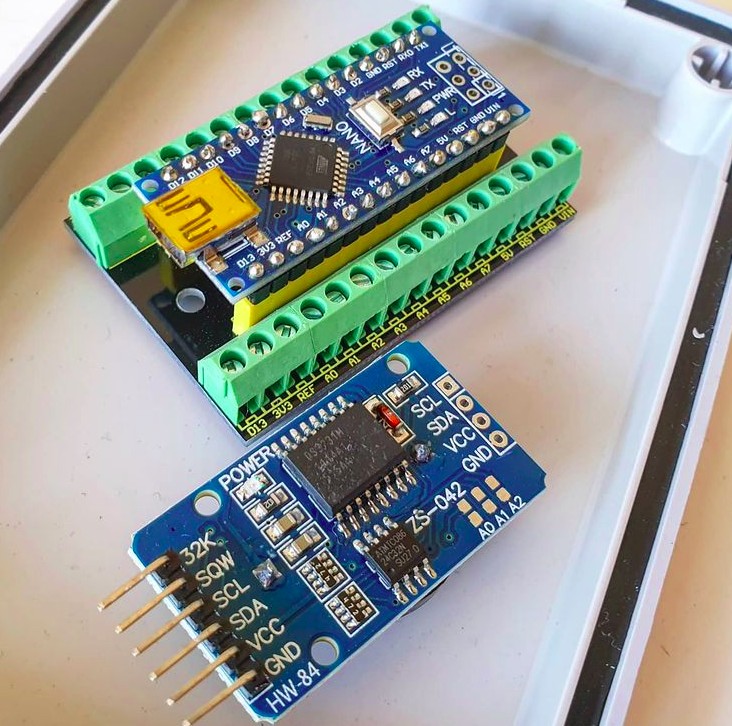
To achieve this a micrcontroller is combined with a Real Time Clock module, providing a battery backed time source that once synced (for example to an NTP time source) maintains current time even when device is switched off.
Arduino Nano in pin breakout board with DS3231 Real Time Clock Module
Arduino DS1307/3231 RTC modules have supporting libraries (for example RTCLib from Adafruit) to obtain current time usually in form of:
DateTime now = rtc.now();
Where DateTime object provides an API to return specific time elements:
Is an event scheduled (at a specific point in time)?
In C function overloading can be used to provide multiple interfaces to an isScheduled() method according to timer precision / time source type :
bool isScheduled(int h);
bool isScheduled(int h, int d);
bool isScheduled(int m, int h, int d);
bool isScheduled(unsigned long ts);

(Where h = hour, m = minute, d = week day)
Most users of Unix based systems are familiar with “timestamp” a 32bit unsigned long representing elapsed seconds since a fixed point in time, the Unix Epoch which occurred 1970-01-01 00:00:00 UTC.
We can obtain current timestamp on Linux via command line with date command:
stevee@ideapad-530S:~$ date +%s
1620155520
A timestamp as a time source can be used with any timer definition, whether point in time or recurring. It has advantage (compared to using numeric representations of individual time elements) that a single long number can be used for computation and conversion and we don’t need to worry about problems like variable number of days in month or leap years.
1970-01-01 was a Thursday, dividing timestamp by 86400 (number of seconds in a day: 24 * 60 * 60) gives number of days since epoch, adding 4 shifts start day to Sun and modulo 7 returns day of week.
To check if a timestamp is within range of one or more on/off time pairs (specified in hh:mm format as uint8_t Min; uint8_t Hour;) first we convert all time elements to elapsed seconds:
// convert fully qualified timestamp to elapsed secs from previous midnight
unsigned long elapsedTime = ts % SECS_PER_DAY;
unsigned long s1, s2, onTime, offTime;
// check each timeArray on/off pair
for (int i = 0; i < _timeArray->n; i++)
{
s1 = _timeArray->onTime[i].Min * SECS_PER_MIN;
s2 = _timeArray->onTime[i].Hour * SECS_PER_HOUR;
onTime = s1 + s2;
s1 = _timeArray->offTime[i].Min * SECS_PER_MIN;
s2 = _timeArray->offTime[i].Hour * SECS_PER_HOUR;
offTime = s1 + s2;
if (elapsedTime >= onTime && elapsedTime <= offTime)
{
return true;
}
}
Conclusion
While TimedDevice library is non-blocking (it does not technique like delay()) it is not truely asynchronous or event driven as each device implementing a timer must poll for an event on each iteration of loop().
This could constrained to checking once per second/minute/hour but perhaps a better architecture would be to use either RTC DS3231 squarewave or Arduino internal timer to register and trigger an interrupt with an associated handler only when an event is due to occur.
Similarly if either a very large number of events are scheduled, or a large set of timed devices created, it would be sensible to register these with a scheduler (akin to a CPU scheduler) tasked with sorting, prioritising and actioning event queue in an efficient way, which might utilise a multi-threaded approach on multi-core CPU architectures.
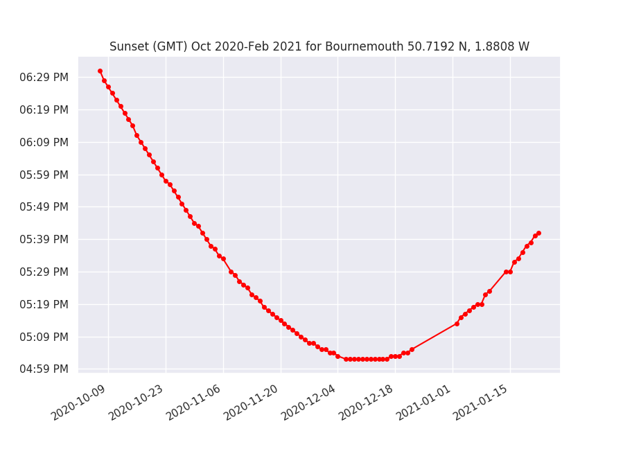
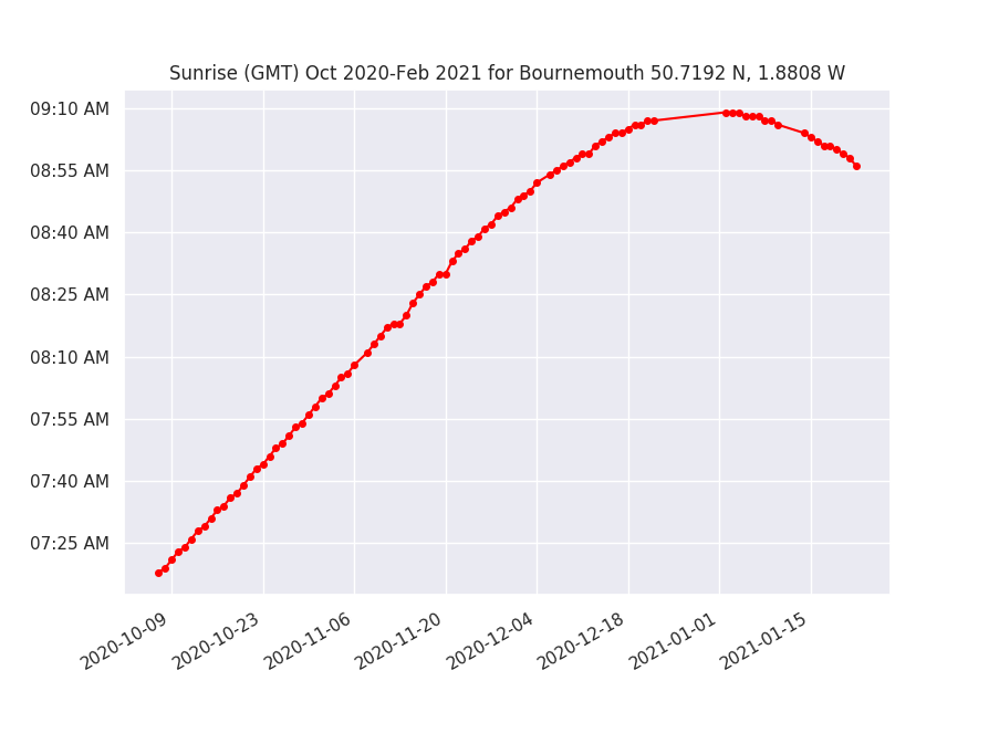
We can use Python Pandas & Mathplotlib libraries to quickly visualise sunrise / sunset timing data, but how to plot time as a number on a graph?
Sunrise / Sunset times are computed on my Arduino Weather Station using SunMoon library ( https://github.com/sfrwmaker/sunMoon ). Incredible that such a tiny 8 bit machine architecture can run this relatively complex algorithm with ease.
Data is logged every 30 mins to daily files stored on SD card in JSON text format.
stevee@ideapad-530S:~/Arduino/projects$ ls  ./data/weather/*.TXT | head -3
./data/weather/20200816.TXT
./data/weather/20200817.TXT
./data/weather/20200818.TXT
Once files are transferred to a Linux computer, a bash script pre-processor (a useful technique on large datasets where syntax modifications are necessary) is used to reformat data as valid array of JSON objects –
stevee@ideapad-530S:~/Arduino/projects$ cat weather_preprocess.bash
#!/bin/bash

for f in data/weather/*.TXT; do
    j="${f%.*}"
    grep "^\[" $f | sed 's/\[//g' | sed 's/\]/,/g' | sed '$ s/.$//' | sed '$ s/.$//'  > $j.json
    sed -i '1 i\\[' $j.json
    echo "]" >> $j.json
    echo $j.json
done
JSON data is an array of objects where each row represents a single log entry indexed by unix timestamp.
Columns represent sensor & computed data – temperature, humidity, air pressure, sun elevation, surise / sunset time and moon phase.
stevee@ideapad-530S:~/Arduino/projects/python$ head -20 ../data/weather/20201015.json
[
{"ts":1602720026,"t":15.5,"h":88,"l":986,"p":102141,"t2":18.8,"a":0.414837,"w":697,"el":-47.86353,"az":2.618189,"lat":50.7192,"lon":-1.8808,"sr":"07:31","ss":"18:14","mn":28},
{"ts":1602720059,"t":15.5,"h":88,"l":988,"p":102140,"t2":18.8,"a":0.166463,"w":692,"el":-47.85925,"az":2.82748,"lat":50.7192,"lon":-1.8808,"sr":"07:31","ss":"18:14","mn":28},
...
Assuming a working Python (v2x) installation and dependencies (Pandas, Mathplorlib, Datetime) are present, we include required libraries and import data from file using Pandas creating a DataFrame in memory table structure –
import os
import json

import matplotlib as mpl
import matplotlib.dates as mdates
import matplotlib.pyplot as plt
import matplotlib.dates as mdates
import pandas as pd
from datetime import datetime as dt

days_to_extract = 90;
path = "../data/weather/"
files = []
frames = []

### Data file path and file format
for (path, dirs, f) in os.walk(path):
    files = [ fi for fi in f if fi.endswith(".json") ]

### Load JSON data
def load_json_data(filepath, frames):
    with open(filepath) as f:
        d = json.load(f)
        df = pd.DataFrame(d)
        frames.append(df)

### process n days datafiles
for f in files:
    filename = path+f
    bits = os.path.splitext(f)
    datestr = bits[0]
    dtm = datetime.strptime(datestr, '%Y%m%d')
    if dtm >= datetime.now()-timedelta(days=days_to_extract):
    load_json_data(filename,frames)

# complete dataset as DataFrame
df = pd.concat(frames)
In dataset although frequency for sunrise / set times is daily, these are actually logged every 30 mins, creating many duplicate entries –
To get one entry per day sunrise/set timing column data is resampled to daily frequency ( .resample(‘1D’) ) and any null rows are dropped with .dropna().
This is equivilent to a relational database roll-up or group by query.
sr = df['sr'].resample('1D').min().dropna()
ss = df['ss'].resample('1D').min().dropna()
Now we have a single daily time entry row indexed by date.
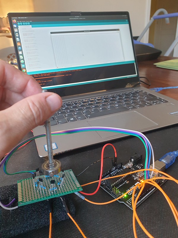
A ring of 8 magnetic digital hall sensors (one per cardinal direction) are activated by a rotating neodymium magnet attached to a shaft, creating a simple rotary encoder.
Hall Effect Magnetic Sensor array connected to Arduino UNO microcontroller.
Input Pull-Up Resistors
Each hall effect sensor is wired to a digital micro-controller pin.
To prevent “floating”, input pin state is biased HIGH using pull-up resistors .
External pull-up 10k resistors are connected between hall effect sensor 5v+ and digital out pins.
If no external resistors are present GPIO pins should be setup as INPUT_PULLUP activating microcontroller internal 20k pull up resistor.
Polling for Active Pin
Each iteration of loop() reads input pins to determine active sensor.
// current and previous active sensor pin
int active = NULL;
int lastActive = NULL;

void loop() {

  int v;
  active = 0;

  for(int i = 3; i <= 10; i++)
  {
    v = digitalRead(i);

    if (v == 0)
    {
      active = i;
    }
  }
  if (active == 0) // magnet between sensor positions
  {
      active = lastActive;
  }
  if (active != lastActive)
  {
    Serial.print(active);
    Serial.print("\t");
    Serial.println(directionLabel[active-3]);
  }

  lastActive = active;
}
Variables are maintained to track current and previous activation, direction is updated on position change.
If magnet is between sensor positions and no pin is active, last active position is reported.
Compass Direction Labels
Finally pin number is translated to direction (“N”, “NE”, “E” etc) by indexing into an ordered character pointer array.
Instead of polling (reading sensors on each loop() iteration) we can minimise processing and power consumption by updating direction only when magnet position changes.
Less power is consumed reading current position from a variable in flash memory compared to reading each sensor input pin – decoupling logic to maintain position from code reporting current value increases efficiency.
To setup pin-change interrupts for digital pins 3 – 10 :
volatile int irqState = 0;
unsigned long lastIrq;
int irqDelay = 100; // millisecs

ISR (PCINT0_vect)
{
  irqState = 1;
}

ISR(PCINT2_vect)
{
  irqState = 1;
}

void setupPinChangeInterrupt()
{
  cli();

  // 1 – Turn on Pin Change Interrupts
  PCICR |= 0b00000001;      // turn on port b (PCINT0 – PCINT7) pins D8 - D13
  PCICR |= 0b00000100;      // turn on port d (PCINT16 – PCINT23) pins D0 - D7

  // 2 – Choose Which Pins to Interrupt ( 3 mask registers correspond to 3 INT ports )
  PCMSK0 |= 0b00000111;    // turn on pins D8,D9,D10
  PCMSK2 |= 0b11111000;    // turn on pins D3 - D7 (PCINT19 - 23)

  sei();                     // turn on interrupts
}
A full example of setting up Arduino pin change interrupts, checking state and reading pins from data register can be found on github and there’s a useful guide here.
Now in loop() we can check for active pin only when interrupt event occurs, software de-bounce timeout prevents multiple repeat activations:
void loop() {

  if (irqState == 1 && (millis() - lastIrq > irqDelay))
  {

    // check for active pin...

    lastIrq = millis();
    irqState = 0;
  }
}
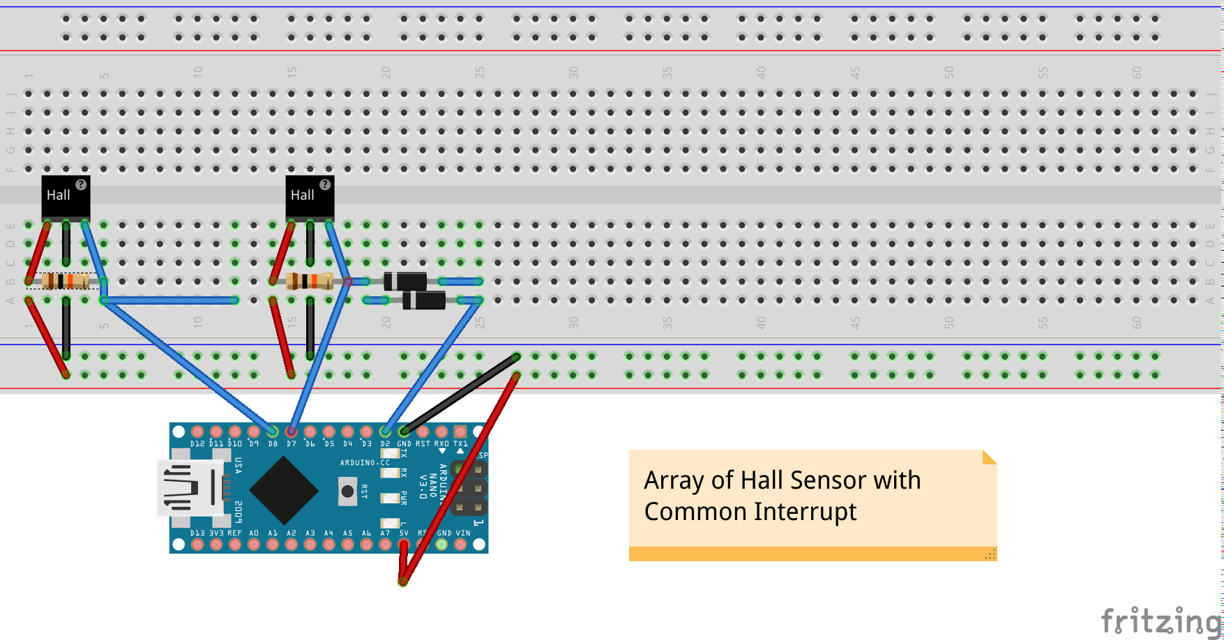
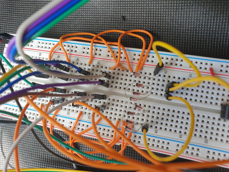
Hardware Common Interrupt
A more portable solution can be implemented in hardware by adding a common interrupt line from each Hall Sensor input, isolating switch input with a diode which conducts only in one direction.
Now a change to any sensor input causes common interrupt (pin D2) to go LOW, signalling to micro-controller to check and update active magnet position.
A single external interrupt can be handled by Arduino Uno/Nano pin D2
attachInterrupt(0, pin2IRQ, FALLING);
Power consumption can be reduced further by implementing deep sleep between sensor change interrupts, waking only to update state or transmit position data at intervals.
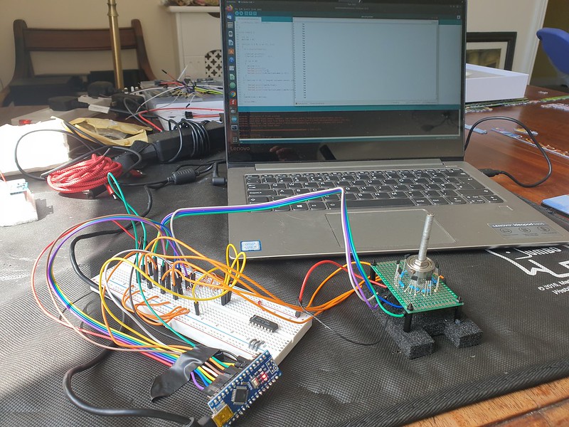
Arduino Nano v3 micro-controller tracking interrupt triggered magnetic switch position
Units range is changed to 360 divided into sub-divisions of 10 and 45 (8 compass directions).
User Interface (UI) Data Provisioning
A finished product might transmit data wirelessly using LORA, Wifi, Bluetooth or 433mhz RF.
For prototype testing we can use serialToWebsocket.py a script based on Python’s PySerial library to capture serial console output and relay this to a websocket.
python3 serialToWebsocket.py
connected to: /dev/ttyUSB0

3	S
5	SW
4	W
6	NW
We can use Python to run a simple webserver to develop and test our interface –
MQTT is a lightweight messaging protocol suitable for embedded and IOT devices.
Websockets ( RFC6455 – https://tools.ietf.org/html/rfc6455 ) is socket programming for internet, an evolution of browser / web server HTTP enabling real-time bidirectional data exchange and binary messaging.
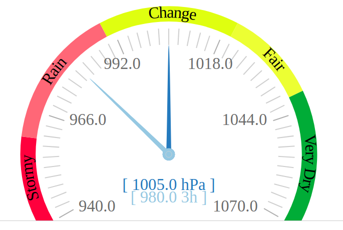
How do we interface a MQTT enabled IOT sensor device with a web browser interface displaying a real time graph chart?
A real time web based barometric air pressure chart interface created with WebSockets and D3.js
Introduction to WebSockets – Real Time TCP Sockets for Internet
With modern browser engines and responsive web UI technologies built on HTML5, SVG and JavaScript frameworks, sophisticated visualisation, display and dashboard reporting capabilities have emerged.
Responsive Web UI runs in any browser installed device – laptop, dekstop, tablet or mobile, without need to install additional software or prepare application code for specific device architectures.
HTTP browser clients essentially implement a polling request/response technique for retrieving and updating HTML format webpages.
Due to need to establish a connection for each new request, HTTP is not well suited to real time or high volume messaging, charting or visualisation applications.
Although AJAX (asynchronous JavaScipt XML) and REST, SOAP API programming overcome this to a certain extent these methods are relatively inefficient for some use cases due to protocol overhead.
With Websockets, TCP network socket programming becomes possible in a browser client application.
Clients can establish a network socket connection, this channel remains open and two-way data exchange including binary messaging formats takes place.
Sockets are well established in UNIX and Windows OS client/server programming, but are relatively new to the web.
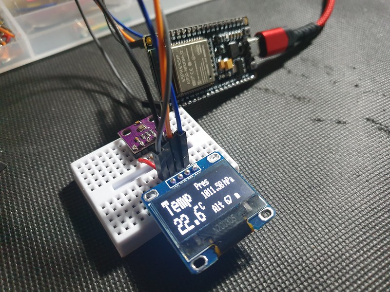
Arduino ESP32 Barometer Sensor MQTT Device
An ESP32 microcontroller with BMP280 environmental sensor and OLED LCD display
An environmental sensor based on an Expressif ESP32 micro-controller and BMP280 Bosch sensor reads air pressure, temperature and altitude –
#include <Adafruit_BMP280.h>

Adafruit_BMP280 bmp;

void setup() {

  if (!bmp.begin()) {
    Serial.println(F("Could not find a valid BMP280 sensor, check wiring!"));
    while (1);
  }

  /* Default settings from datasheet. */
  bmp.setSampling(Adafruit_BMP280::MODE_NORMAL,     /* Operating Mode. */
                  Adafruit_BMP280::SAMPLING_X2,     /* Temp. oversampling */
                  Adafruit_BMP280::SAMPLING_X16,    /* Pressure oversampling */
                  Adafruit_BMP280::FILTER_X16,      /* Filtering. */
                  Adafruit_BMP280::STANDBY_MS_500); /* Standby time. */

}

void loop() {

  Serial.print(F("Temperature = "));
  Serial.print(bmp.readTemperature());
  Serial.println(" *C");

  Serial.print(F("Pressure = "));
  Serial.print(bmp.readPressure()/100); //displaying the Pressure in hPa, you can change the unit
  Serial.println(" hPa");

  Serial.print(F("Approx altitude = "));
  Serial.print(bmp.readAltitude(1019.66)); //The "1019.66" is the pressure(hPa) at sea level in day in your region
  Serial.println(" m");                    //If you don't know it, modify it until you get your current altitude

  display.clearDisplay();
  float t = bmp.readTemperature();           //Read temperature in C
  float p = bmp.readPressure()/100;         //Read Pressure in Pa and conversion to hPa
  float a = bmp.readAltitude(1019.66);      //Calculating the Altitude, the "1019.66" is the pressure in (hPa) at sea level at day in your region

  delay(2000);
}
Data is communicated over Wifi to an MQTT messaging server.
On server we require a relay to subscribe for MQTT messages on sensor device channel, establish a WebSocket and write data to connected browser clients.
An implementation in NodeJS requires WS, MQTT and events libraries:
// setup Websocket Server
const WebSocket = require('ws');
var ws_host = "192.168.1.127";
var ws_port = "8080";
const wss = new WebSocket.Server({ host: ws_host, port: ws_port });
var ws = null;

// Setup MQTT Client
// mqtt[s]://[username][:password]@host.domain[:port]
var mqtt = require('mqtt'), url = require('url');
var mqtt_url = url.parse(process.env.MQTT_URL || 'mqtt://192.168.1.127:1883');
var auth = (mqtt_url.auth || ':').split(':');
var url = "mqtt://" + mqtt_url.host;
var mqtt_channel_in = "esp8266.in";
var mqtt_channel_out = "esp8266.out";

var options = {
    port: mqtt_url.port,
    clientId: 'mqttjs_' + Math.random().toString(16).substr(2, 8),
    username: 'mqtt',
    password: '__mqtt_password__',
    keepalive: 60,
    reconnectPeriod: 1000,
    protocolId: 'MQIsdp',
    protocolVersion: 3,
    clean: true,
    encoding: 'utf8'
};
NodeJS is event based, when an MQTT message is received it can be forwarded to all connected WebSocket clients:
mqttClient.on('message', function sendMsg(topic, message, packet) {

  console.log(topic + ": " + message);

  var eventListeners = require('events').EventEmitter.listenerCount(mqttClient,'message');
  console.log(eventListeners + " Listner(s) listening to mqttClient message event");
  console.log(mqttClient.rawListeners('message'));

  wss.clients.forEach(function each(ws) {
    if (ws.isAlive === false) return ws.terminate();
    console.log(data);
    ws.send(data+" ");
  });

});
MQTT allows many subscribers to receive topic messages.
Python Eclipse Paho MQTT client with Mongo DB
A client based on Eclipse Paho ( https://www.eclipse.org/paho/ ) developed in Python might add persistence by writing to a Mongo DB datastore:
### Python MQTT client
### Subscribes to an MQTT topic receiving JSON format messages in format:
###    [{"ts":1586815920,"temp":22.3,"pressure":102583,"alt":76}]
###
### Writes receieved JSON data to a mongo DB collection
###
import paho.mqtt.client as mqtt
import json
import pymongo

mqtt_server = "192.168.1.127"
mqtt_port = 1883
mqtt_keepalive = 60
mqtt_channel_out = "esp8266.out"
mqtt_channel_in = "esp8266.in"

mongo_server = "mongodb://localhost:27017/"
mongo_db = "weather"
mongo_collection = "sensorData"

def on_connect(client,userdata,flags,rc):
    print("Connected with result code:"+str(rc))
    print ("MQTT server: "+mqtt_server+", port: "+str(mqtt_port));
    print ("MQTT topic: "+mqtt_channel_out);
    client.subscribe(mqtt_channel_out)

def on_message(client, userdata, msg):
    print(msg.payload)
    parsed_json = (json.loads(msg.payload))
    res = sensorData.insert_one(parsed_json[0])

mongoClient = pymongo.MongoClient(mongo_server)
mydb = mongoClient[mongo_db]
sensorData = mydb[mongo_collection]

mqttClient = mqtt.Client()
mqttClient.connect(mqtt_server,mqtt_port,mqtt_keepalive);

mqttClient.on_connect = on_connect
mqttClient.on_message = on_message

mqttClient.loop_forever()
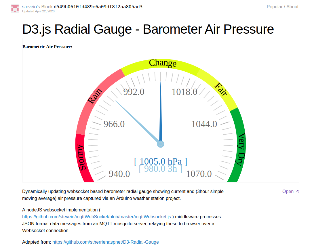
Web Browser Client – D3.js WebSocket Real Time Chart
Necessary cookies help make a website usable by enabling basic functions like page navigation and access to secure areas of the website. The website cannot function properly without these cookies.
We do not use cookies of this type.
Marketing cookies are used to track visitors across websites. The intention is to display ads that are relevant and engaging for the individual user and thereby more valuable for publishers and third party advertisers.
We do not use cookies of this type.
Analytics cookies help website owners to understand how visitors interact with websites by collecting and reporting information anonymously.
We do not use cookies of this type.
Preference cookies enable a website to remember information that changes the way the website behaves or looks, like your preferred language or the region that you are in.
We do not use cookies of this type.
Unclassified cookies are cookies that we are in the process of classifying, together with the providers of individual cookies.
We do not use cookies of this type.
Cookies are small text files that can be used by websites to make a user's experience more efficient. The law states that we can store cookies on your device if they are strictly necessary for the operation of this site. For all other types of cookies we need your permission. This site uses different types of cookies. Some cookies are placed by third party services that appear on our pages.