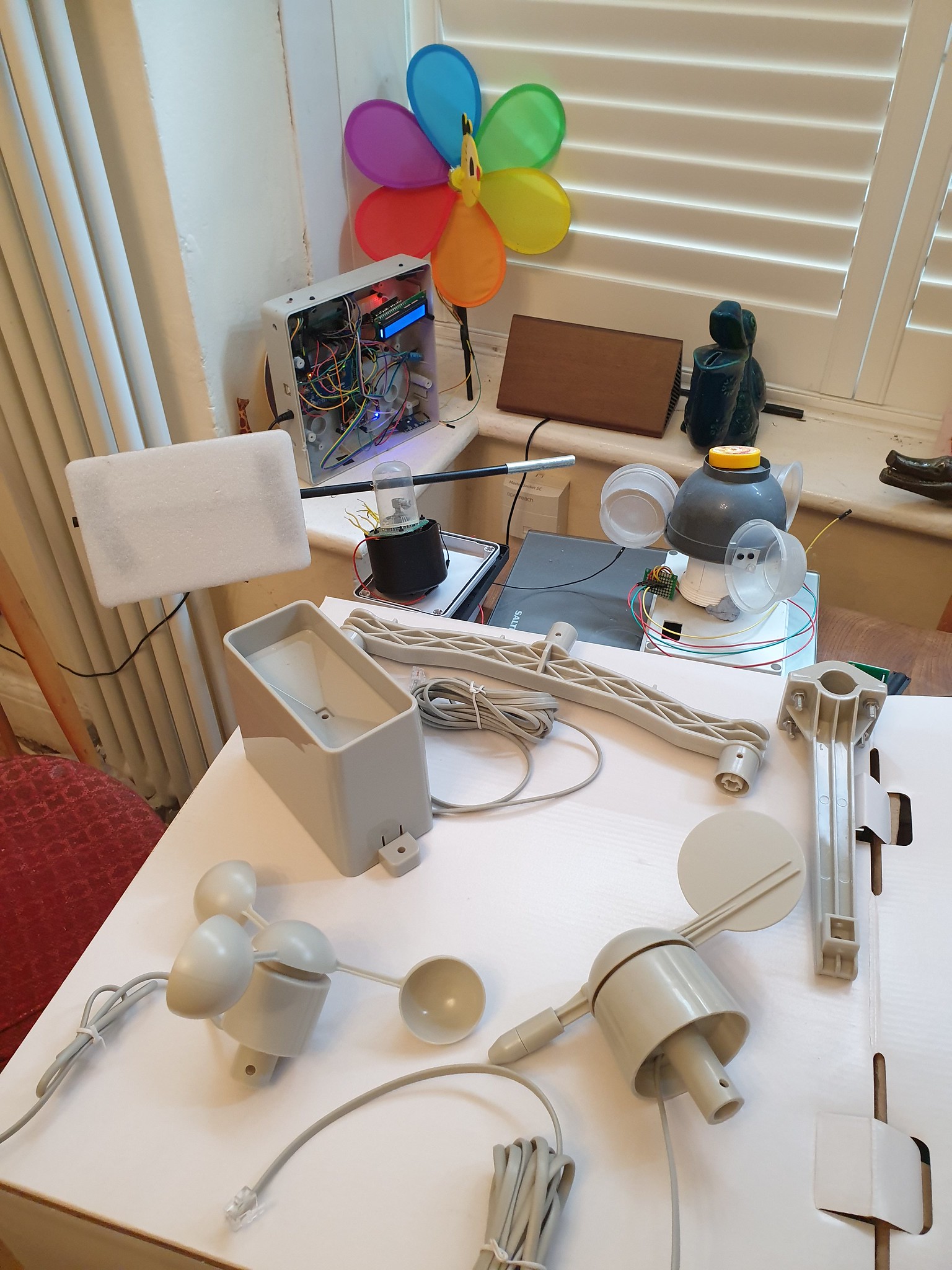
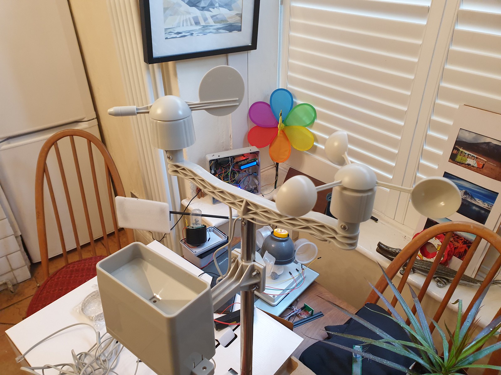
Wind and Rain sensor kit newly arrived from SparkFun Electronics to upgrade an Arduino Weather Station project.
SparkFun Weather Sensor Kit, DIY prototypes, Arduino Weather Station
Also pictured are earlier DIY prototypes – a childrens bee wind spinner with hall effect sensor to count rotations, an anemometer made from recycled plastic packaging utilising a IR Led optical rotary encoder and a wind vane with eight fixed directional magnetic switches.
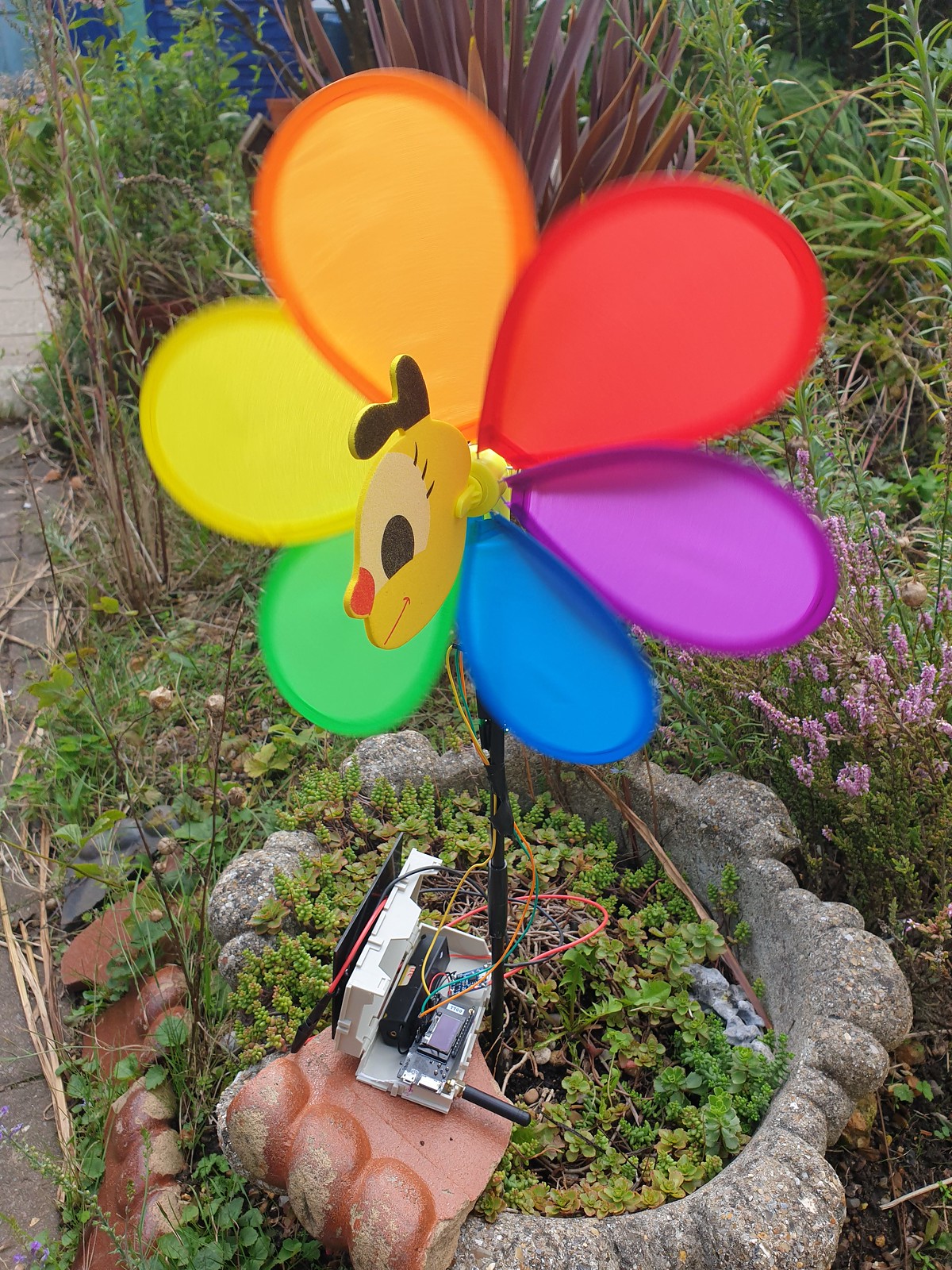
Bee Windmill Anemometer with ESP32 LoRa Transmitter running on single 3.3v Li-Ion cell.
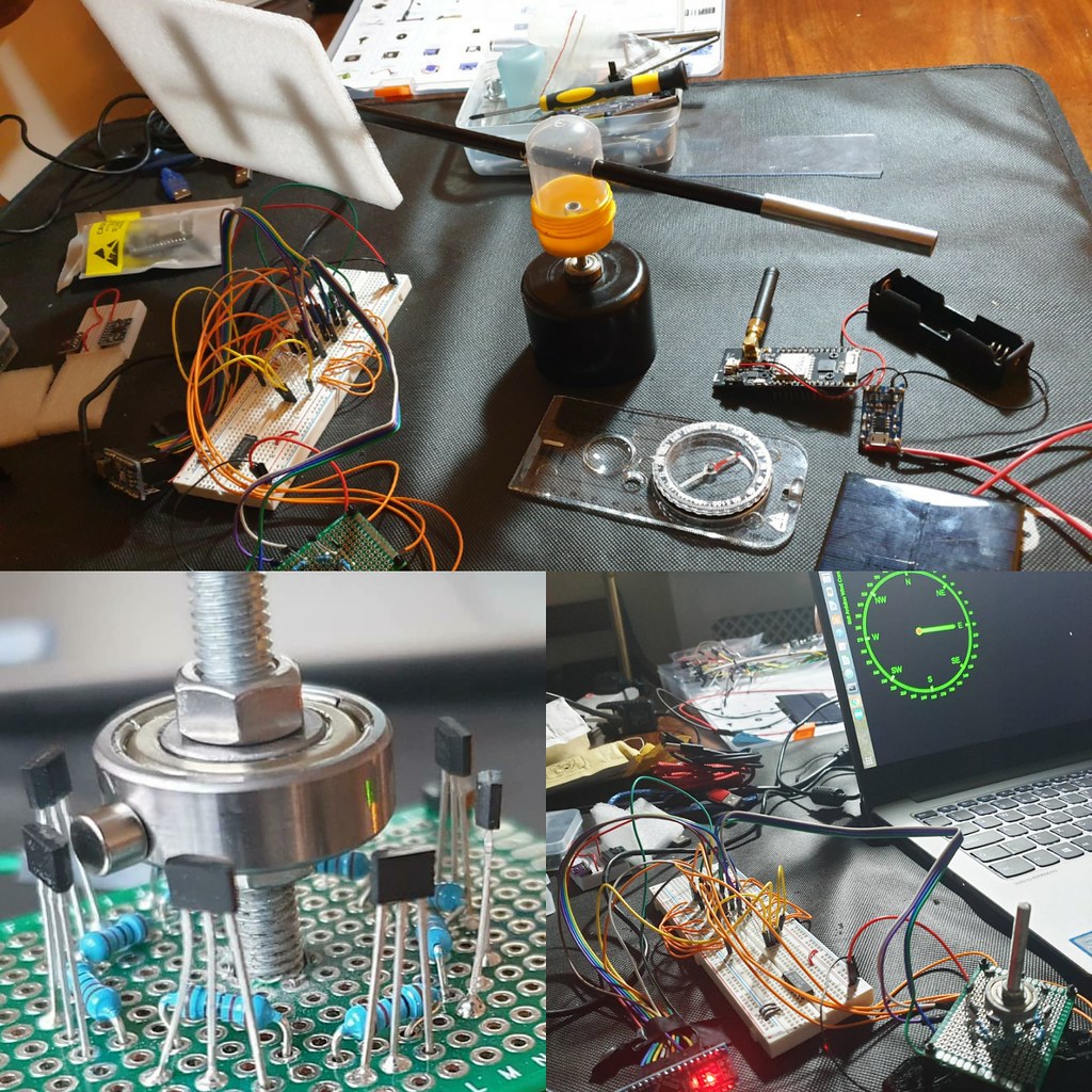
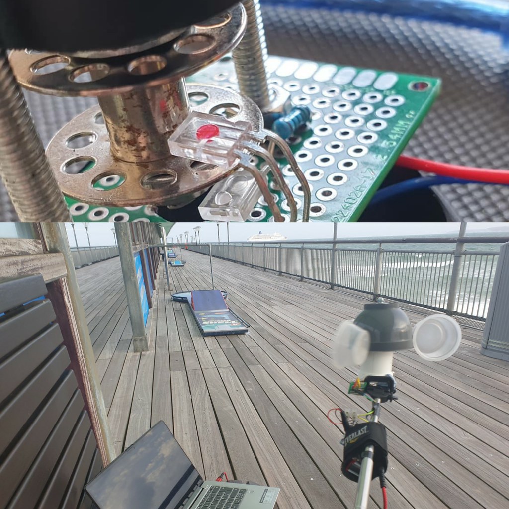
8 Durection WInd Vane with magnetic hall sensor array and WebSocket TCP web browser interface.ESP8266 Anemometer with optical IR Led sensor, wifi connectivity and D3.js websocket provisioned UI.
Weather station projects are a popular accessible introduction to microelectronics; a microcontroller and sensors can be found at low cost, modular hardware design results in easy assembly and open software platforms like Arduino IDE streamline packaging and deployment of code to devices.
Analysing real time or historical time series data, from weather sensors is a lot of fun. Frameworks like R Project for Math Stats: https://www.r-project.org/ ) and Python, Pandas, Numpy & Mathplotlib provide implementations of most alogirithms and convenient data structures for importing & manipulating data.
Techniques and methods are transferable and can be applied to other domains or ontologies – finanicial, accounting data for example.
With advent of 3d modelling & printing it is also feasible for an enthusiast to design and fabricate via a 3d printer custom sensor components, perhaps using template models downloaded from repos like ThingiVerse.
In competition marine OpenWind are defining what smart network connected sensors can achieve utilising Bluetooth LE to make near real time wind data available on smartphone.
Assembled SparkFun Weather Sensor Kit
Ideal for enthusiast or educator SparkFun Weather kit comes wihout circuitry, microcontroller or software. An add-on PCB designed for use with Arduino / ESP32 can be purchased or Datasheet Technical Specs provide reference sensor circuit designs, not significantly complex due to use of magnetic reed switch and variable resistance technology.
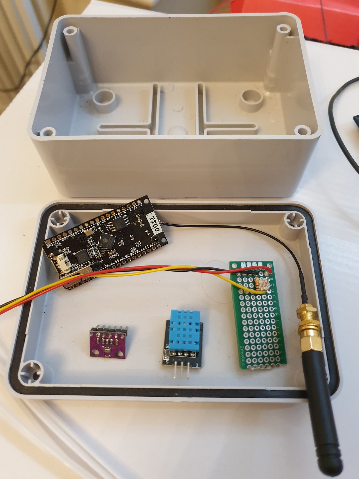
MCU Sensor Control & Relay Unit – IP67 Weather Proof Enclosure, ESP32 TTGO LoRa microcontroller, light, temperature and air pressure sensors.
Traditionally 433MHz RF has been used for base station to transmitter devices. A popular project is to use Arduino, a cheap 433Mhz receiver and a library to read data from a commercial weather station designed for use with manufacturers display, enabling this data to be provisioned to the cloud.
For data transmission non GPRS (cellular) options include Bluetooth LE (range ~100 metres) or LoRa (Long Range Low Power Network – range between 300 – 10km depending on antenae) offering cableless wireless connectivity allowing remote sensor situation with no associated network costs.
At data layer WebSockets and MQTT for IOT devices are challenging serial protocols as defacto lightweight, reliable & easy to implement transport relays.
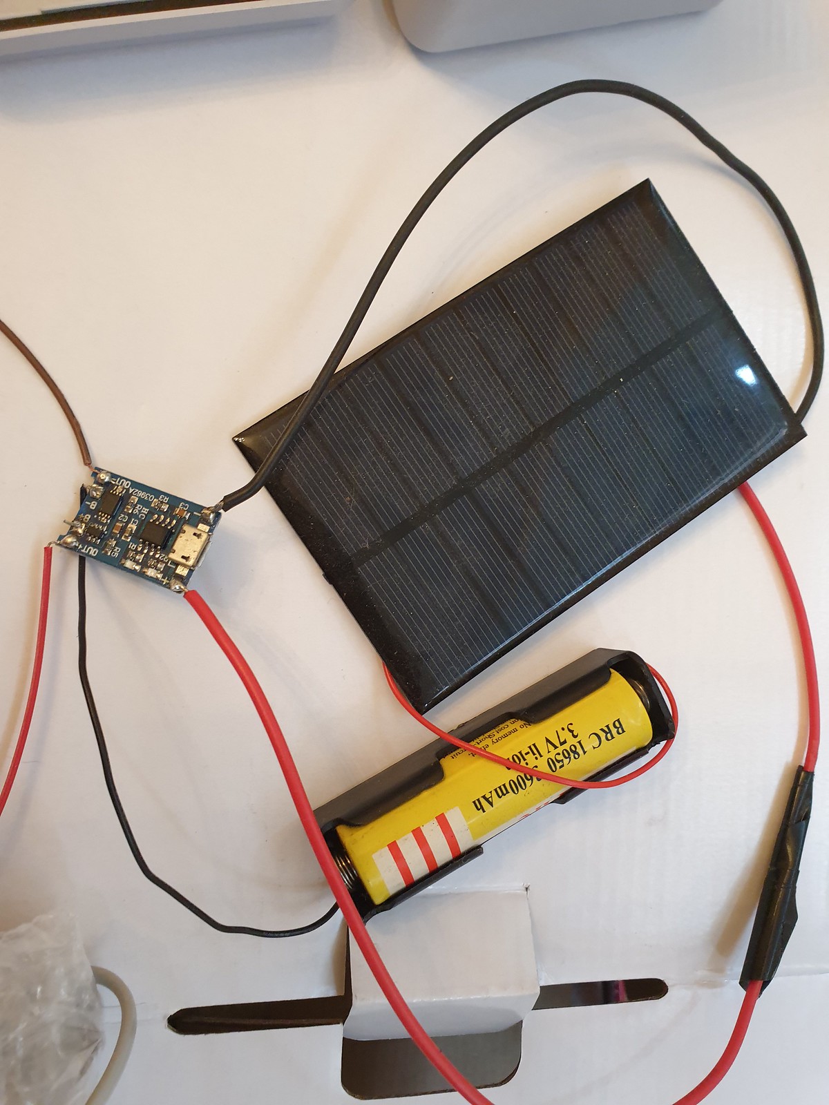
Apart from range and connectivity goals of low power consumption for efficient and long battery running time combined with solar charging enable devices to run standalone for long periods.
Is a single 3.3v Li-Ion Battery Cell Sufficient? TP405 Charging Module & Solar Panel
Weather Stations have applications beyond meteorology in smart agriculture, industrial, safety monitoring and for wind or wave based leisure pursuits.
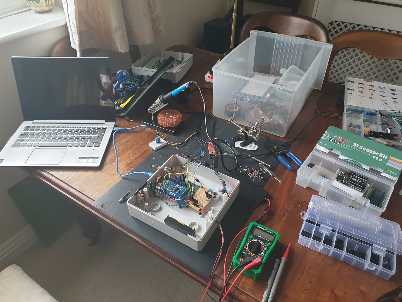
Assembling DIY Arduino Mega Weather Station v1.0
More generally Internet of things wireless networked smart sensor platforms can be used for many purposes and combined with AI and Machine Learning algorithms useful insight and patterns within data can be analysed, classified and predicted.
SparkFun Smart ETextiles & Conductive Thread Kit
Personally, I really enjoyed SparkFun Arduino LilyPad e-textile, smart fabrics and conductive thread kit, so looking forward to now spinning up the Weather Station sensors!
What types of sensor can be used for a weather vane? How to track angular position using a rotary encoder? How easy is calibration? What coding considerations for a weather station wind direction project?
Mesopotamian base-60 number system resulted in our idea of 360° in a full circle. Early compasses described 32 points and eight cardinal directions of wind, serving as navigational aids for maritime exploration.
References recorded in ancient China as early as 139 BC described “wind observing fan”. In classical Greece astronomer Andronicus constructed a weather vane at “tower of winds” in Athens. Weather vanes were known in many places of antiquity.
The word “vane” derives from Old English “fane” (Germanic Fahne) signifying “cloth, banner, flag” all of which can be deployed as visual wind direction indicators.
In modern times, absolute and incremental encoders are sensor devices measuring rotary position (angle) and motion. Resolution, precision and accuracy have distinct meaning.
Absolute encoders maintain position during power off or device reset. Incremental motion encoder data is relative, sensors of this type require “homing” (passing a known position) to calibrate.
Contactless magnetic encoders track a dipole magnet attached to a rotating shaft above sensor, recording rotational angle and direction through a full turn of 360° with high resolution and precision.
Internally hall sensors measure angular position of a magnetic field presented at surface, converting this to a voltage.
On chip digital signal processing (DSP) amplifies and filters planar field data before conversion by Analogue to Digital conversion (ADC).
Having no mechanical friction leads to long expected life span.
A wide operating temperature range (-40 Deg.C to 150 Deg.C) and environmental tolerances (~80% humidity) allow for a wide potential application range.
2/3 wire I2C/SPI programmable interfaces provide standardised micro-controller connectivity and control.
Several commercial wind vanes targeted at maritime applications deploy a 360° potentiometer connected directly to vane shaft.
Having a compact, space efficient design, high resolution (degrees of direction) can be tracked.
Detent (stops or clicks) add rotational resistance and a fixed set of positions but increase friction.
Electro-mechanical contacts are subject to mechanical wear and surface corrosion of contact track impacting accuracy, durability and longevity.
Optical Encoder
Optical incremental encoders – IR LED / Sensor pair with a spinning disk interrupter are accurate at very high RPM rates with low sensor latency (rise time).
Resolution is determined by interrupt light “chopper” disk design and relative position is measured by counting rotational sensor ticks.
Quadrature or two channel encoding, with a phase offset, is employed to determine rotational direction.
Calibration, including between device reset/power off is a challenge – sensor pulse counting during rotation must be relative to a fixed/known initial position.
Magnetic Sensor Array
Early compasses recorded 32 points to indicate winds as a navigational aid to sailors.
Wiring 32 sensors together requires considerable soldering & assembly skill. If 4 or 8 bit resolution is sufficient, magnetic linear hall or reed switches might be used – both are contactless, low cost and widely available.
Sensors arranged in a ring array activated by a rotating magnet allow a micro-controller to track position changes.
One approach is to use polling and a GPIO pin per sensor. Pin change interrupts can also be used for state notification.
An analogue multiplexer (CD4051) reduces number of required input pins to 4 (3 address pins, 1 data), optionally a common interrupt enables this to work with an event (interrupt) driven model.
Sensor Implementation – Polling vs Event Model
Polling, reading position at a set frequency (interval), provides consistency and allows simple computation analysis – roll-up averages for example. Higher frequency sampling results in higher precision.
In event model – an interrupt is triggered when sensor state (position) changes.
Recording position data only when direction changes is a low power consumption approach, extending operating duration of a battery powered device, especially on windless days.
To implement event driven design with a multiplexer poses a challenge, at circuit level a common interrupt line wired with isolating diodes to each sensor is required.
A change to any individual sensor triggers an interrupt, micro-controller can then check each multiplexer channel to determine position.
Calibration – how to determine magnetic north?
A compass bearing is required to determine direction relative to cardinal directions.
Wind vanes in a fixed position are manually calibrated. Electronic sensor devices can resolve orientation relative to magnetic compass.
Wind direction is defined by World Geodetic System (WGS) as direction from which wind blows and is measured clockwise from geographical north, namely, true north (meteorology) or in aviation reporting relative to magentic north.
Visualisation – Wind Rose and Polar Distribution Charts
Wind roses, a type of polar bar chart provide a visualisation of wind distribution: direction and magnitude (velocity) frequency at a location over a given time interval.
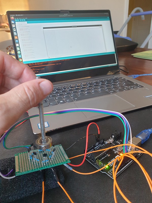
A ring of 8 magnetic digital hall sensors (one per cardinal direction) are activated by a rotating neodymium magnet attached to a shaft, creating a simple rotary encoder.
Hall Effect Magnetic Sensor array connected to Arduino UNO microcontroller.
Input Pull-Up Resistors
Each hall effect sensor is wired to a digital micro-controller pin.
To prevent “floating”, input pin state is biased HIGH using pull-up resistors .
External pull-up 10k resistors are connected between hall effect sensor 5v+ and digital out pins.
If no external resistors are present GPIO pins should be setup as INPUT_PULLUP activating microcontroller internal 20k pull up resistor.
Polling for Active Pin
Each iteration of loop() reads input pins to determine active sensor.
// current and previous active sensor pin
int active = NULL;
int lastActive = NULL;

void loop() {

  int v;
  active = 0;

  for(int i = 3; i <= 10; i++)
  {
    v = digitalRead(i);

    if (v == 0)
    {
      active = i;
    }
  }
  if (active == 0) // magnet between sensor positions
  {
      active = lastActive;
  }
  if (active != lastActive)
  {
    Serial.print(active);
    Serial.print("\t");
    Serial.println(directionLabel[active-3]);
  }

  lastActive = active;
}
Variables are maintained to track current and previous activation, direction is updated on position change.
If magnet is between sensor positions and no pin is active, last active position is reported.
Compass Direction Labels
Finally pin number is translated to direction (“N”, “NE”, “E” etc) by indexing into an ordered character pointer array.
Instead of polling (reading sensors on each loop() iteration) we can minimise processing and power consumption by updating direction only when magnet position changes.
Less power is consumed reading current position from a variable in flash memory compared to reading each sensor input pin – decoupling logic to maintain position from code reporting current value increases efficiency.
To setup pin-change interrupts for digital pins 3 – 10 :
volatile int irqState = 0;
unsigned long lastIrq;
int irqDelay = 100; // millisecs

ISR (PCINT0_vect)
{
  irqState = 1;
}

ISR(PCINT2_vect)
{
  irqState = 1;
}

void setupPinChangeInterrupt()
{
  cli();

  // 1 – Turn on Pin Change Interrupts
  PCICR |= 0b00000001;      // turn on port b (PCINT0 – PCINT7) pins D8 - D13
  PCICR |= 0b00000100;      // turn on port d (PCINT16 – PCINT23) pins D0 - D7

  // 2 – Choose Which Pins to Interrupt ( 3 mask registers correspond to 3 INT ports )
  PCMSK0 |= 0b00000111;    // turn on pins D8,D9,D10
  PCMSK2 |= 0b11111000;    // turn on pins D3 - D7 (PCINT19 - 23)

  sei();                     // turn on interrupts
}
A full example of setting up Arduino pin change interrupts, checking state and reading pins from data register can be found on github and there’s a useful guide here.
Now in loop() we can check for active pin only when interrupt event occurs, software de-bounce timeout prevents multiple repeat activations:
void loop() {

  if (irqState == 1 && (millis() - lastIrq > irqDelay))
  {

    // check for active pin...

    lastIrq = millis();
    irqState = 0;
  }
}
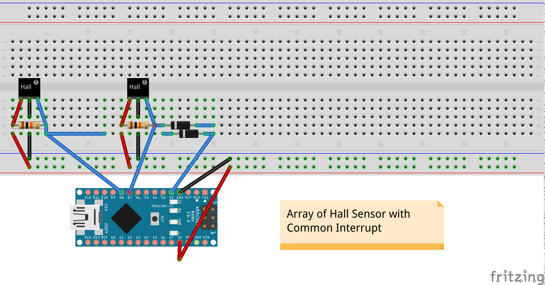
Hardware Common Interrupt
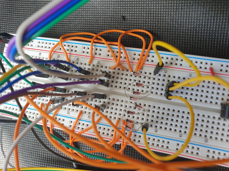
A more portable solution can be implemented in hardware by adding a common interrupt line from each Hall Sensor input, isolating switch input with a diode which conducts only in one direction.
Now a change to any sensor input causes common interrupt (pin D2) to go LOW, signalling to micro-controller to check and update active magnet position.
A single external interrupt can be handled by Arduino Uno/Nano pin D2
attachInterrupt(0, pin2IRQ, FALLING);
Power consumption can be reduced further by implementing deep sleep between sensor change interrupts, waking only to update state or transmit position data at intervals.
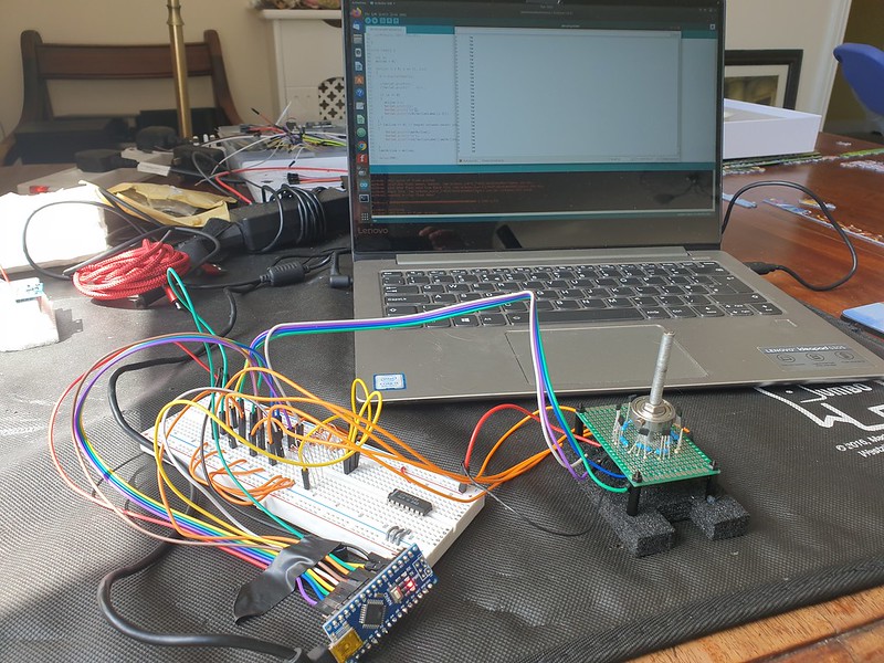
Arduino Nano v3 micro-controller tracking interrupt triggered magnetic switch position
Units range is changed to 360 divided into sub-divisions of 10 and 45 (8 compass directions).
User Interface (UI) Data Provisioning
A finished product might transmit data wirelessly using LORA, Wifi, Bluetooth or 433mhz RF.
For prototype testing we can use serialToWebsocket.py a script based on Python’s PySerial library to capture serial console output and relay this to a websocket.
python3 serialToWebsocket.py
connected to: /dev/ttyUSB0

3	S
5	SW
4	W
6	NW
We can use Python to run a simple webserver to develop and test our interface –
MQTT is a lightweight messaging protocol suitable for embedded and IOT devices.
Websockets ( RFC6455 – https://tools.ietf.org/html/rfc6455 ) is socket programming for internet, an evolution of browser / web server HTTP enabling real-time bidirectional data exchange and binary messaging.
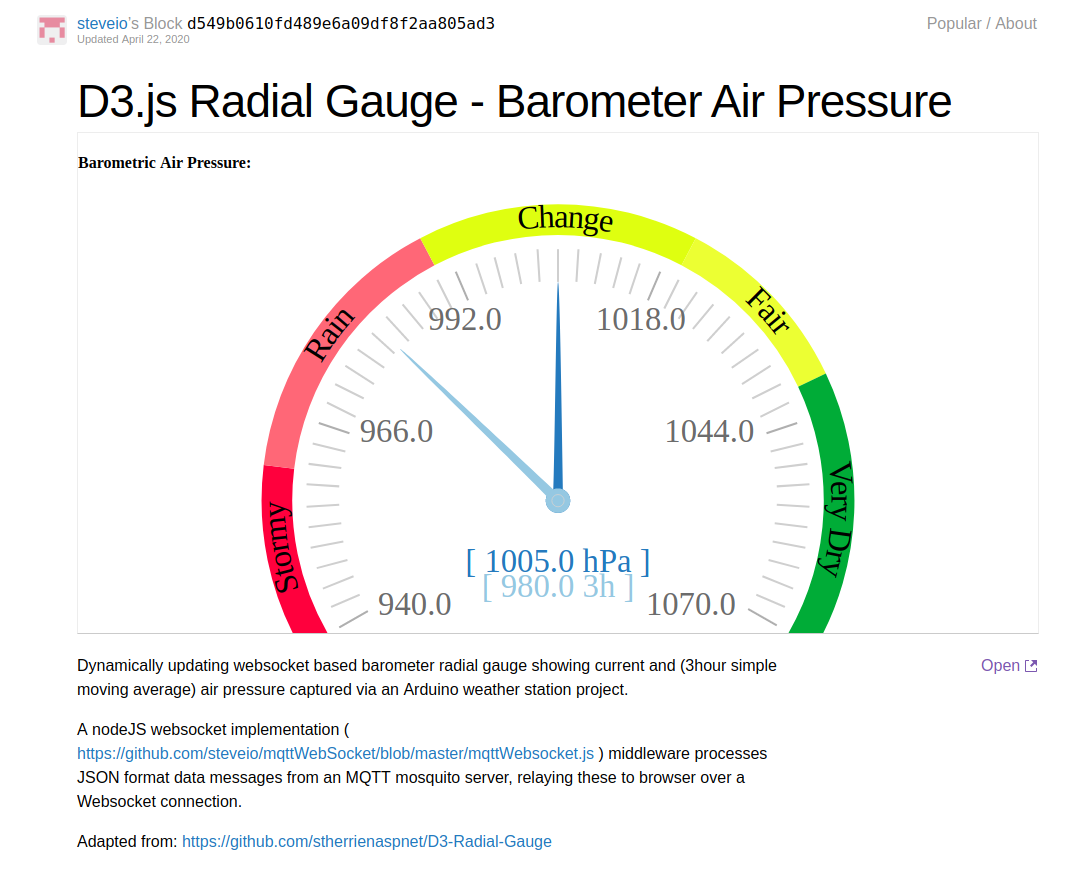
How do we interface a MQTT enabled IOT sensor device with a web browser interface displaying a real time graph chart?
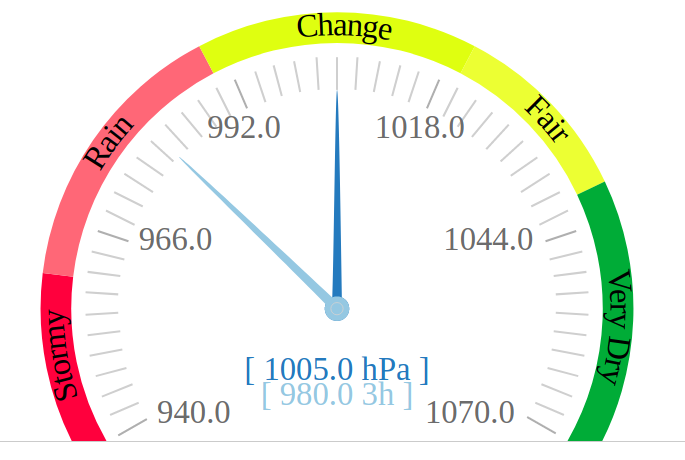
A real time web based barometric air pressure chart interface created with WebSockets and D3.js
Introduction to WebSockets – Real Time TCP Sockets for Internet
With modern browser engines and responsive web UI technologies built on HTML5, SVG and JavaScript frameworks, sophisticated visualisation, display and dashboard reporting capabilities have emerged.
Responsive Web UI runs in any browser installed device – laptop, dekstop, tablet or mobile, without need to install additional software or prepare application code for specific device architectures.
HTTP browser clients essentially implement a polling request/response technique for retrieving and updating HTML format webpages.
Due to need to establish a connection for each new request, HTTP is not well suited to real time or high volume messaging, charting or visualisation applications.
Although AJAX (asynchronous JavaScipt XML) and REST, SOAP API programming overcome this to a certain extent these methods are relatively inefficient for some use cases due to protocol overhead.
With Websockets, TCP network socket programming becomes possible in a browser client application.
Clients can establish a network socket connection, this channel remains open and two-way data exchange including binary messaging formats takes place.
Sockets are well established in UNIX and Windows OS client/server programming, but are relatively new to the web.
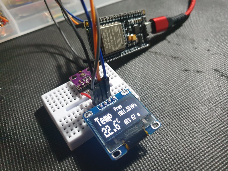
Arduino ESP32 Barometer Sensor MQTT Device
An ESP32 microcontroller with BMP280 environmental sensor and OLED LCD display
An environmental sensor based on an Expressif ESP32 micro-controller and BMP280 Bosch sensor reads air pressure, temperature and altitude –
#include <Adafruit_BMP280.h>

Adafruit_BMP280 bmp;

void setup() {

  if (!bmp.begin()) {
    Serial.println(F("Could not find a valid BMP280 sensor, check wiring!"));
    while (1);
  }

  /* Default settings from datasheet. */
  bmp.setSampling(Adafruit_BMP280::MODE_NORMAL,     /* Operating Mode. */
                  Adafruit_BMP280::SAMPLING_X2,     /* Temp. oversampling */
                  Adafruit_BMP280::SAMPLING_X16,    /* Pressure oversampling */
                  Adafruit_BMP280::FILTER_X16,      /* Filtering. */
                  Adafruit_BMP280::STANDBY_MS_500); /* Standby time. */

}

void loop() {

  Serial.print(F("Temperature = "));
  Serial.print(bmp.readTemperature());
  Serial.println(" *C");

  Serial.print(F("Pressure = "));
  Serial.print(bmp.readPressure()/100); //displaying the Pressure in hPa, you can change the unit
  Serial.println(" hPa");

  Serial.print(F("Approx altitude = "));
  Serial.print(bmp.readAltitude(1019.66)); //The "1019.66" is the pressure(hPa) at sea level in day in your region
  Serial.println(" m");                    //If you don't know it, modify it until you get your current altitude

  display.clearDisplay();
  float t = bmp.readTemperature();           //Read temperature in C
  float p = bmp.readPressure()/100;         //Read Pressure in Pa and conversion to hPa
  float a = bmp.readAltitude(1019.66);      //Calculating the Altitude, the "1019.66" is the pressure in (hPa) at sea level at day in your region

  delay(2000);
}
Data is communicated over Wifi to an MQTT messaging server.
On server we require a relay to subscribe for MQTT messages on sensor device channel, establish a WebSocket and write data to connected browser clients.
An implementation in NodeJS requires WS, MQTT and events libraries:
// setup Websocket Server
const WebSocket = require('ws');
var ws_host = "192.168.1.127";
var ws_port = "8080";
const wss = new WebSocket.Server({ host: ws_host, port: ws_port });
var ws = null;

// Setup MQTT Client
// mqtt[s]://[username][:password]@host.domain[:port]
var mqtt = require('mqtt'), url = require('url');
var mqtt_url = url.parse(process.env.MQTT_URL || 'mqtt://192.168.1.127:1883');
var auth = (mqtt_url.auth || ':').split(':');
var url = "mqtt://" + mqtt_url.host;
var mqtt_channel_in = "esp8266.in";
var mqtt_channel_out = "esp8266.out";

var options = {
    port: mqtt_url.port,
    clientId: 'mqttjs_' + Math.random().toString(16).substr(2, 8),
    username: 'mqtt',
    password: '__mqtt_password__',
    keepalive: 60,
    reconnectPeriod: 1000,
    protocolId: 'MQIsdp',
    protocolVersion: 3,
    clean: true,
    encoding: 'utf8'
};
NodeJS is event based, when an MQTT message is received it can be forwarded to all connected WebSocket clients:
mqttClient.on('message', function sendMsg(topic, message, packet) {

  console.log(topic + ": " + message);

  var eventListeners = require('events').EventEmitter.listenerCount(mqttClient,'message');
  console.log(eventListeners + " Listner(s) listening to mqttClient message event");
  console.log(mqttClient.rawListeners('message'));

  wss.clients.forEach(function each(ws) {
    if (ws.isAlive === false) return ws.terminate();
    console.log(data);
    ws.send(data+" ");
  });

});
MQTT allows many subscribers to receive topic messages.
Python Eclipse Paho MQTT client with Mongo DB
A client based on Eclipse Paho ( https://www.eclipse.org/paho/ ) developed in Python might add persistence by writing to a Mongo DB datastore:
### Python MQTT client
### Subscribes to an MQTT topic receiving JSON format messages in format:
###    [{"ts":1586815920,"temp":22.3,"pressure":102583,"alt":76}]
###
### Writes receieved JSON data to a mongo DB collection
###
import paho.mqtt.client as mqtt
import json
import pymongo

mqtt_server = "192.168.1.127"
mqtt_port = 1883
mqtt_keepalive = 60
mqtt_channel_out = "esp8266.out"
mqtt_channel_in = "esp8266.in"

mongo_server = "mongodb://localhost:27017/"
mongo_db = "weather"
mongo_collection = "sensorData"

def on_connect(client,userdata,flags,rc):
    print("Connected with result code:"+str(rc))
    print ("MQTT server: "+mqtt_server+", port: "+str(mqtt_port));
    print ("MQTT topic: "+mqtt_channel_out);
    client.subscribe(mqtt_channel_out)

def on_message(client, userdata, msg):
    print(msg.payload)
    parsed_json = (json.loads(msg.payload))
    res = sensorData.insert_one(parsed_json[0])

mongoClient = pymongo.MongoClient(mongo_server)
mydb = mongoClient[mongo_db]
sensorData = mydb[mongo_collection]

mqttClient = mqtt.Client()
mqttClient.connect(mqtt_server,mqtt_port,mqtt_keepalive);

mqttClient.on_connect = on_connect
mqttClient.on_message = on_message

mqttClient.loop_forever()
Web Browser Client – D3.js WebSocket Real Time Chart
Necessary cookies help make a website usable by enabling basic functions like page navigation and access to secure areas of the website. The website cannot function properly without these cookies.
We do not use cookies of this type.
Marketing cookies are used to track visitors across websites. The intention is to display ads that are relevant and engaging for the individual user and thereby more valuable for publishers and third party advertisers.
We do not use cookies of this type.
Analytics cookies help website owners to understand how visitors interact with websites by collecting and reporting information anonymously.
We do not use cookies of this type.
Preference cookies enable a website to remember information that changes the way the website behaves or looks, like your preferred language or the region that you are in.
We do not use cookies of this type.
Unclassified cookies are cookies that we are in the process of classifying, together with the providers of individual cookies.
We do not use cookies of this type.
Cookies are small text files that can be used by websites to make a user's experience more efficient. The law states that we can store cookies on your device if they are strictly necessary for the operation of this site. For all other types of cookies we need your permission. This site uses different types of cookies. Some cookies are placed by third party services that appear on our pages.