Categories
circuits Internet of Things microcontrollers sensors Software weather station

Weather Station Wind Vane

What types of sensor can be used for a weather vane? How to track angular position using a rotary encoder? How easy is calibration? What coding considerations for a weather station wind direction project?

Mesopotamian base-60 number system resulted in our idea of 360° in a full circle. Early compasses described 32 points and eight cardinal directions of wind, serving as navigational aids for maritime exploration.

References recorded in ancient China as early as 139 BC described “wind observing fan”. In classical Greece astronomer Andronicus constructed a weather vane at “tower of winds” in Athens. Weather vanes were known in many places of antiquity.

The word “vane” derives from Old English “fane” (Germanic Fahne) signifying “cloth, banner, flag” all of which can be deployed as visual wind direction indicators.

In modern times, absolute and incremental encoders are sensor devices measuring rotary position (angle) and motion. Resolution, precision and accuracy have distinct meaning.

Absolute encoders maintain position during power off or device reset. Incremental motion encoder data is relative, sensors of this type require “homing” (passing a known position) to calibrate.

Lets consider some types of rotary encoder

  • magnetic rotary encoder
  • 360° Potentiometer
  • optical encoder
  • magnetic sensor array

Magnetic Rotary Encoder

Contactless magnetic encoders track a dipole magnet attached to a rotating shaft above sensor, recording rotational angle and direction through a full turn of 360° with high resolution and precision.

Internally hall sensors measure angular position of a magnetic field presented at surface, converting this to a voltage.

On chip digital signal processing (DSP) amplifies and filters planar field data before conversion by Analogue to Digital conversion (ADC).

Having no mechanical friction leads to long expected life span.

A wide operating temperature range (-40 Deg.C to 150 Deg.C) and environmental tolerances (~80% humidity) allow for a wide potential application range.

2/3 wire I2C/SPI programmable interfaces provide standardised micro-controller connectivity and control.

AS5600 Datasheet
MLX90316 Datasheet

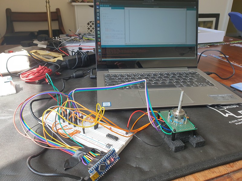
Potentiometer 360 degree

Several commercial wind vanes targeted at maritime applications deploy a 360° potentiometer connected directly to vane shaft.

Having a compact, space efficient design, high resolution (degrees of direction) can be tracked.

Detent (stops or clicks) add rotational resistance and a fixed set of positions but increase friction.

Electro-mechanical contacts are subject to mechanical wear and surface corrosion of contact track impacting accuracy, durability and longevity.

Optical Encoder

Optical incremental encoders – IR LED / Sensor pair with a spinning disk interrupter are accurate at very high RPM rates with low sensor latency (rise time).

Resolution is determined by interrupt light “chopper” disk design and relative position is measured by counting rotational sensor ticks.

Quadrature or two channel encoding, with a phase offset, is employed to determine rotational direction.

Calibration, including between device reset/power off is a challenge – sensor pulse counting during rotation must be relative to a fixed/known initial position.

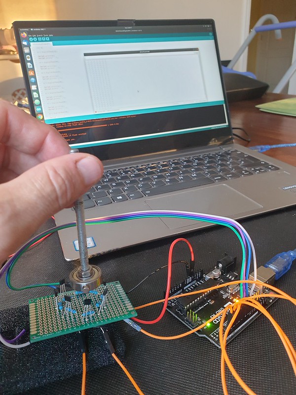
Magnetic Sensor Array

Early compasses recorded 32 points to indicate winds as a navigational aid to sailors.

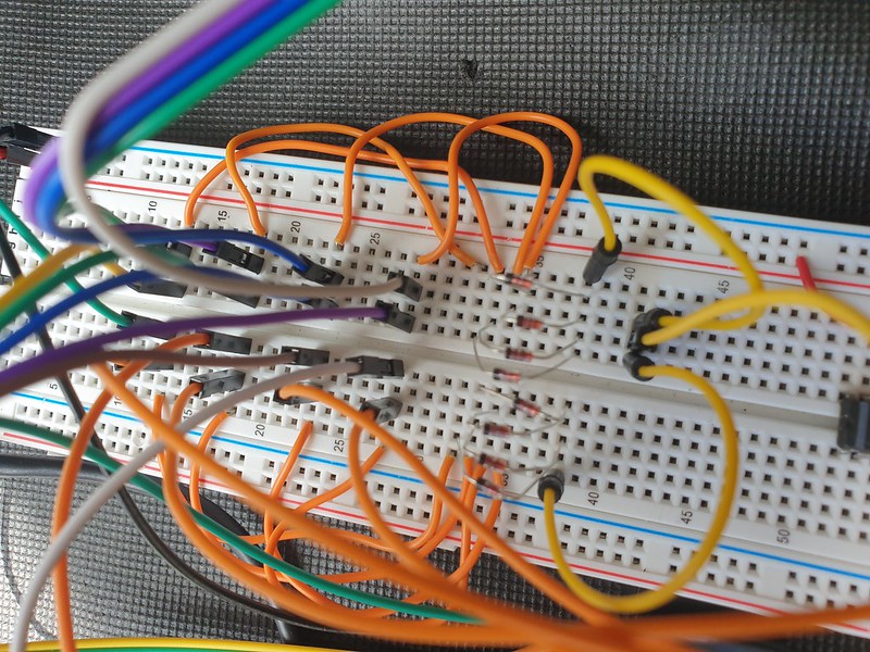
Wiring 32 sensors together requires considerable soldering & assembly skill. If 4 or 8 bit resolution is sufficient, magnetic linear hall or reed switches might be used – both are contactless, low cost and widely available.

Sensors arranged in a ring array activated by a rotating magnet allow a micro-controller to track position changes.

One approach is to use polling and a GPIO pin per sensor. Pin change interrupts can also be used for state notification.

An analogue multiplexer (CD4051) reduces number of required input pins to 4 (3 address pins, 1 data), optionally a common interrupt enables this to work with an event (interrupt) driven model.

Sensor Implementation – Polling vs Event Model

Polling, reading position at a set frequency (interval), provides consistency and allows simple computation analysis – roll-up averages for example. Higher frequency sampling results in higher precision.

In event model – an interrupt is triggered when sensor state (position) changes.

Recording position data only when direction changes is a low power consumption approach, extending operating duration of a battery powered device, especially on windless days.

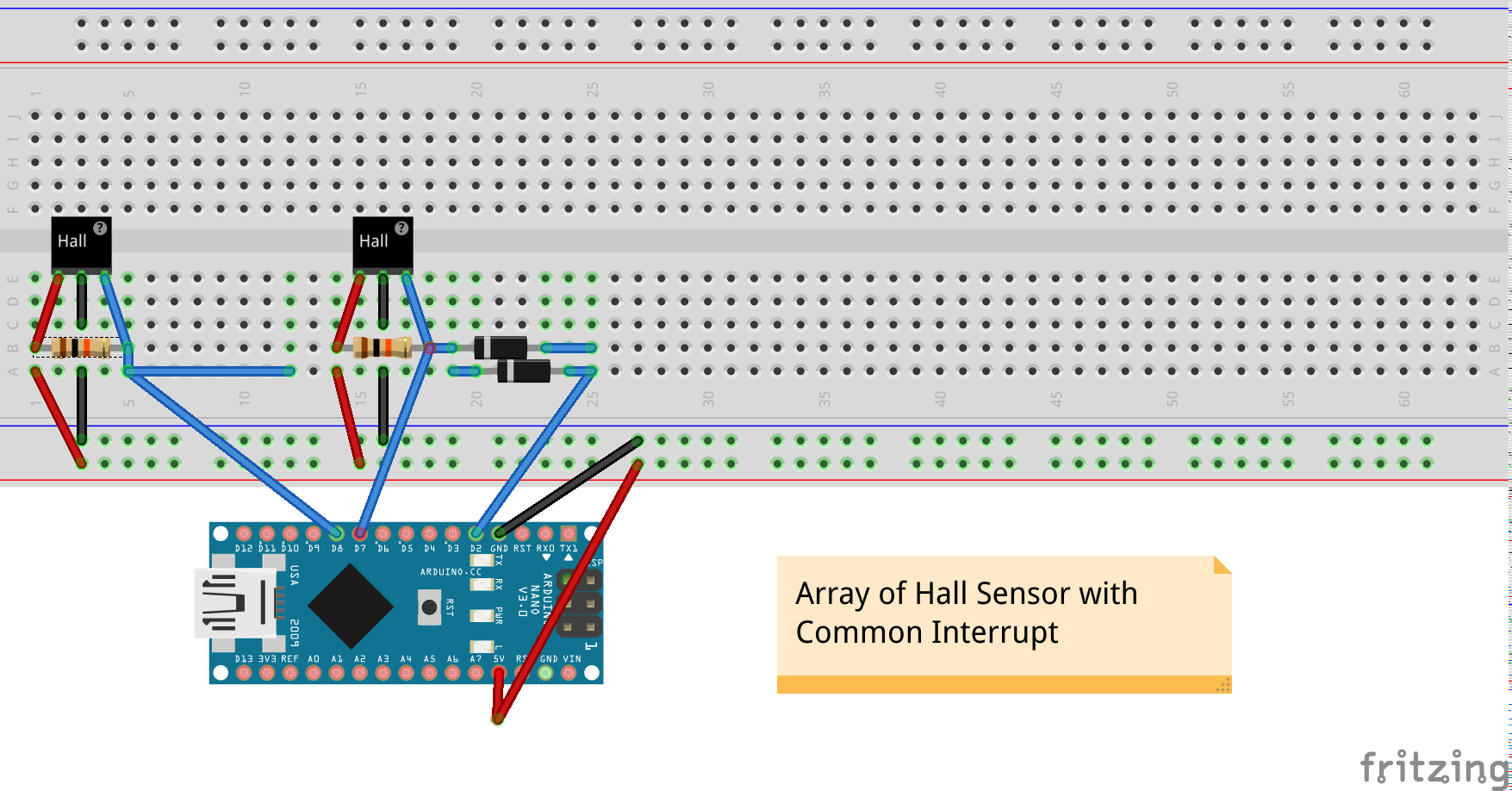
To implement event driven design with a multiplexer poses a challenge, at circuit level a common interrupt line wired with isolating diodes to each sensor is required.

A change to any individual sensor triggers an interrupt, micro-controller can then check each multiplexer channel to determine position.

Calibration – how to determine magnetic north?

A compass bearing is required to determine direction relative to cardinal directions.

Wind vanes in a fixed position are manually calibrated. Electronic sensor devices can resolve orientation relative to magnetic compass.

Wind direction is defined by World Geodetic System (WGS) as direction from which wind blows and is measured clockwise from geographical north, namely, true north (meteorology) or in aviation reporting relative to magentic north. 

Visualisation – Wind Rose and Polar Distribution Charts

Wind roses, a type of polar bar chart provide a visualisation of wind distribution: direction and magnitude (velocity) frequency at a location over a given time interval.

Categories
arduino circuits Coding Internet of Things microcontrollers sensors Software

Weather Vane – Magnetic Sensor Rotary Encoder

A ring of 8 magnetic digital hall sensors (one per cardinal direction) are activated by a rotating neodymium magnet attached to a shaft, creating a simple rotary encoder.

Hall Effect Magnetic Sensor array connected to Arduino UNO microcontroller.

Input Pull-Up Resistors

Each hall effect sensor is wired to a digital micro-controller pin.

To prevent “floating”, input pin state is biased HIGH using pull-up resistors .

External pull-up 10k resistors are connected between hall effect sensor 5v+ and digital out pins.

If no external resistors are present GPIO pins should be setup as INPUT_PULLUP activating microcontroller internal 20k pull up resistor.

Polling for Active Pin

Each iteration of loop() reads input pins to determine active sensor.

// current and previous active sensor pin
int active = NULL;
int lastActive = NULL;

void loop() {

  int v;
  active = 0;

  for(int i = 3; i <= 10; i++)
  {
    v = digitalRead(i);

    if (v == 0)
    {
      active = i;
    }
  }
  if (active == 0) // magnet between sensor positions
  {
      active = lastActive;      
  }
  if (active != lastActive)
  {
    Serial.print(active);
    Serial.print("\t");
    Serial.println(directionLabel[active-3]);
  }

  lastActive = active;
}

Variables are maintained to track current and previous activation, direction is updated on position change.

If magnet is between sensor positions and no pin is active, last active position is reported.

Compass Direction Labels

Finally pin number is translated to direction (“N”, “NE”, “E” etc) by indexing into an ordered character pointer array.

// pin order direction labels
char d0[] = "NE";
char d1[] = "SE";
char d2[] = "E";
char d3[] = "S";
char d4[] = "N";
char d5[] = "W";
char d6[] = "NW";
char d7[] = "SW";

char * directionLabel[] = { d0, d1, d2, d3, d4, d5, d6, d7 };

...
// i == active sensor pin number 3 - 10 
Serial.println(directionLabel[i-3]);

Interrupts – Event Driven

Instead of polling (reading sensors on each loop() iteration) we can minimise processing and power consumption by updating direction only when magnet position changes.

Less power is consumed reading current position from a variable in flash memory compared to reading each sensor input pin – decoupling logic to maintain position from code reporting current value increases efficiency.

On Arduino (Uno, Nano etc) by default specific pins trigger external interrupts. Any GPIO pin can be used as an interrupt trigger with pin change interrupts.

To setup pin-change interrupts for digital pins 3 – 10 :

volatile int irqState = 0;
unsigned long lastIrq;
int irqDelay = 100; // millisecs

ISR (PCINT0_vect) 
{
  irqState = 1; 
}

ISR(PCINT2_vect)
{
  irqState = 1; 
}

void setupPinChangeInterrupt()
{
  cli();

  // 1 – Turn on Pin Change Interrupts
  PCICR |= 0b00000001;      // turn on port b (PCINT0 – PCINT7) pins D8 - D13
  PCICR |= 0b00000100;      // turn on port d (PCINT16 – PCINT23) pins D0 - D7

  // 2 – Choose Which Pins to Interrupt ( 3 mask registers correspond to 3 INT ports )
  PCMSK0 |= 0b00000111;    // turn on pins D8,D9,D10
  PCMSK2 |= 0b11111000;    // turn on pins D3 - D7 (PCINT19 - 23)

  sei();                     // turn on interrupts
}

A full example of setting up Arduino pin change interrupts, checking state and reading pins from data register can be found on github and there’s a useful guide here.

Now in loop() we can check for active pin only when interrupt event occurs, software de-bounce timeout prevents multiple repeat activations:

void loop() {

  if (irqState == 1 &amp;&amp; (millis() - lastIrq > irqDelay))
  {

    // check for active pin...

    lastIrq = millis();
    irqState = 0;
  }
}

Hardware Common Interrupt

A more portable solution can be implemented in hardware by adding a common interrupt line from each Hall Sensor input, isolating switch input with a diode which conducts only in one direction.

Now a change to any sensor input causes common interrupt (pin D2) to go LOW, signalling to micro-controller to check and update active magnet position.

1N4148 High Speed Signal Diode isolate common interrupt line

A single external interrupt can be handled by Arduino Uno/Nano pin D2

attachInterrupt(0, pin2IRQ, FALLING);

Power consumption can be reduced further by implementing deep sleep between sensor change interrupts, waking only to update state or transmit position data at intervals.

Arduino Nano v3 micro-controller tracking interrupt triggered magnetic switch position

Real Time Wind Compass Web Interface

D3.js Wind Compass UI has a design inspired by Dieter Rams who worked for Braun and is single HTML file adapted from a simple clock.

Units range is changed to 360 divided into sub-divisions of 10 and 45 (8 compass directions).

User Interface (UI) Data Provisioning

A finished product might transmit data wirelessly using LORA, Wifi, Bluetooth or 433mhz RF.

For prototype testing we can use serialToWebsocket.py a script based on Python’s PySerial library to capture serial console output and relay this to a websocket.

python3 serialToWebsocket.py 
connected to: /dev/ttyUSB0

3	S
5	SW
4	W
6	NW

We can use Python to run a simple webserver to develop and test our interface –

python -m SimpleHTTPServer 3001

Wind Compass can now be loaded in a browser –

http://127.0.0.1:3001/wsWindCompass.html

UI demo and source code can be found below –

See it in action –

Full source code can on github:

Arduino Wind Vane Sketch:
https://github.com/steveio/arduino/tree/master/WindVane8HallSensor
Wind Compass D3.js Web UI:
https://github.com/steveio/mqttWebSocket/blob/master/wsWindCompass.html
Serial to Websocket Python Script
https://github.com/steveio/arduino/blob/master/python/serialToWebsocket.py