Categories
Internet of Things sensors wearables

Wearables: Mi Band 6 Smart Fitness Tracker

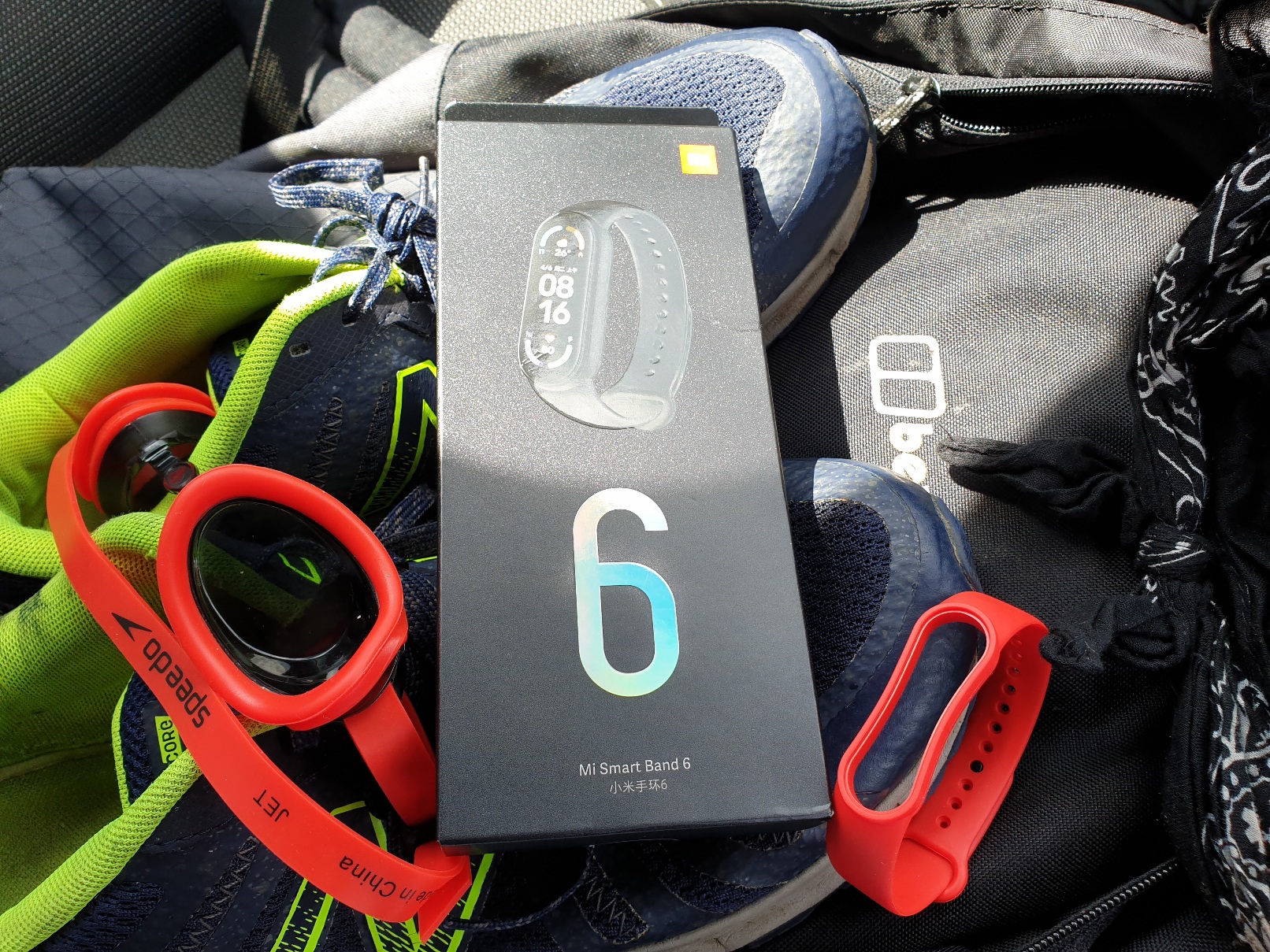
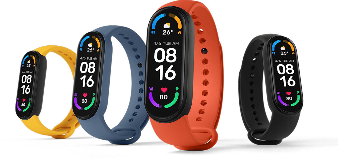
Mi Band 6 is a wearable smart watch / fitness band tracker from Xiaomi with Mi Fit health mobile app.

For a time i’ve looked for an economic sport tracker band or smart watch that is waterproof, swim compatible, syncs with Strava and offers long battery life.

Crucially, what you don’t get with slim lightweight (12.8g) fitness band compared to smart watches from brands like Apple or Garmin is GPS location tracking.

To record route data you must also carry a paired GPS smart phone with Mi Fit app when cycling, running or walking.

Lack of GPS radio conversely helps preserve battery life promised as upto 14 days.

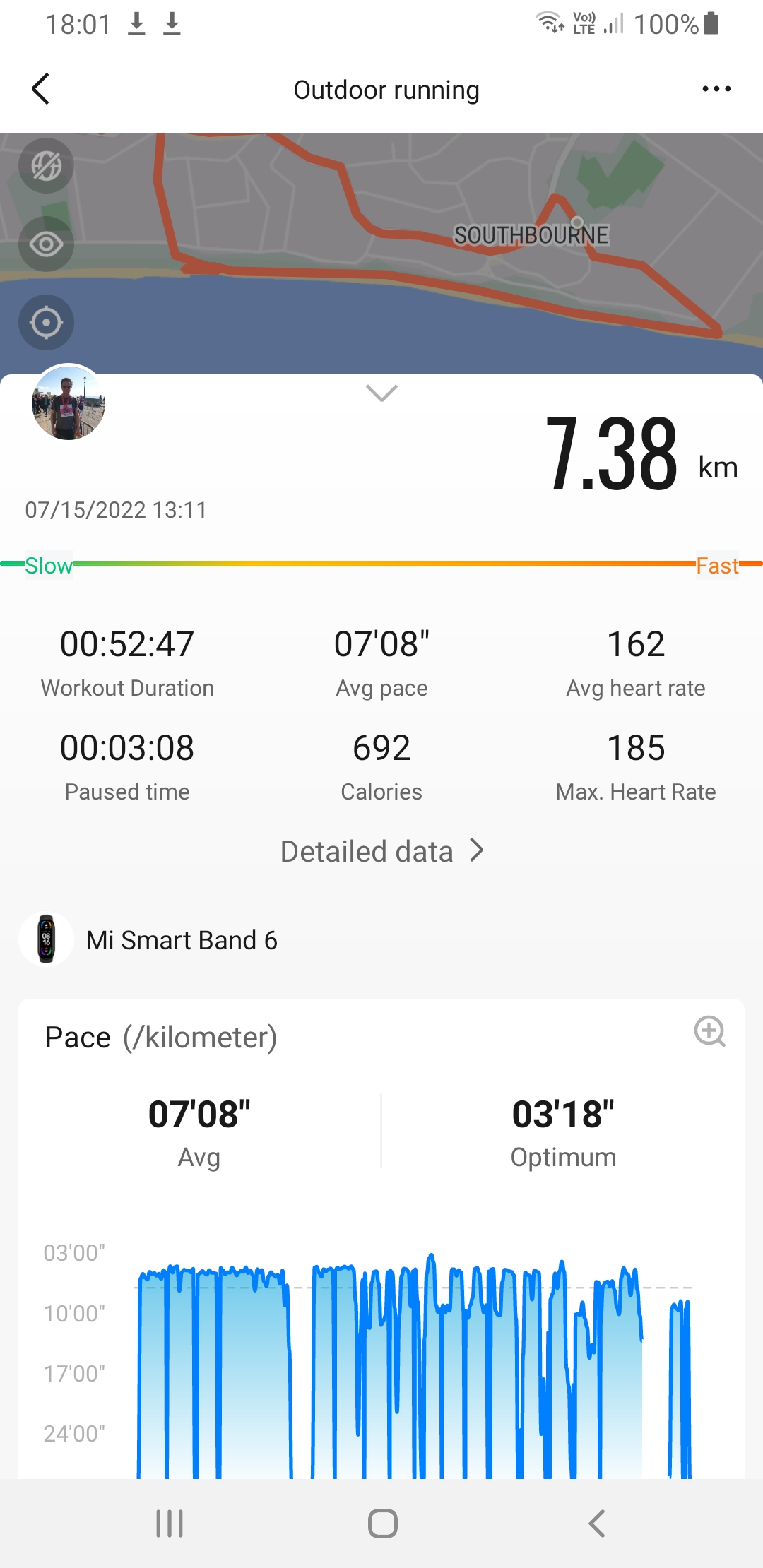
Timing, location and speed data recorded by Mi Fit appeared reasonable accurate for cycling, running & walking.

Strava is a social platform offering privacy options to obscure route start / end points, Mi Fit by default does not share route data.

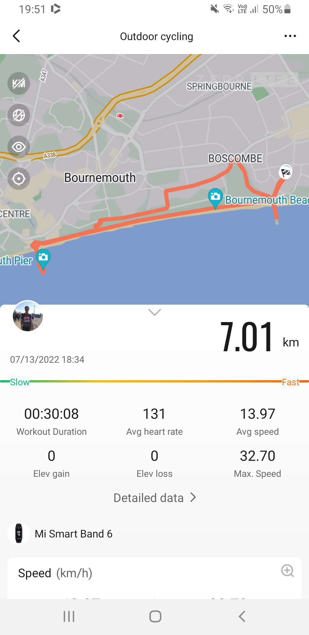
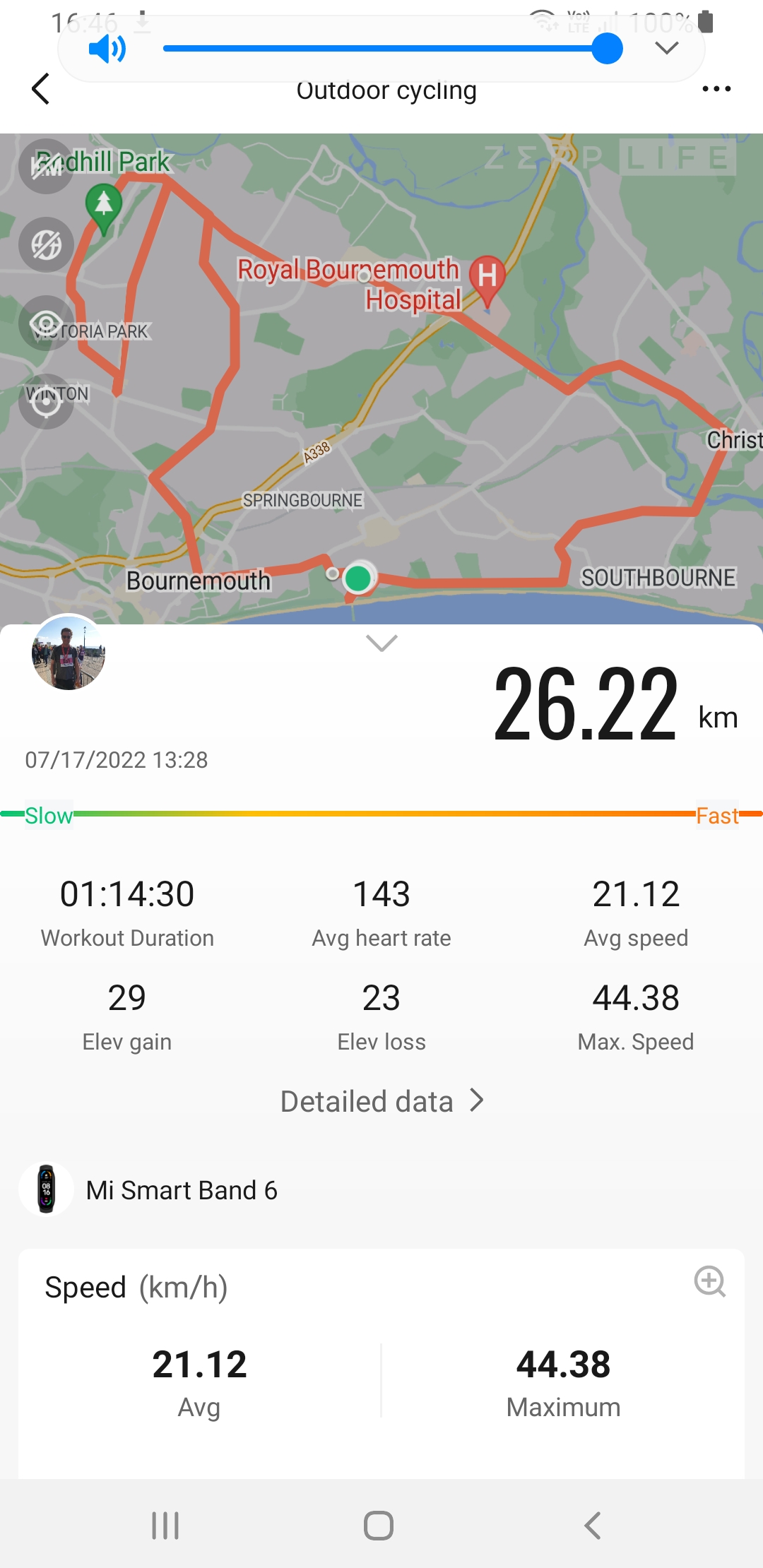
GPS Elevation was not accurate beyond ~100 metre range. Multiple climbs / descents of between 20 and 150 metres were not tracked correctly (sea level promenade route displayed incorrectly as 90 metres).

Also, there is no indication from device sensors or mapping provider of incline to describe stage climb / descent.

Smart bands promise to remove need to carry a physical wallet and keys but at present Mi Band 6 only supports AliPay / WeChat which is not widely accepted in UK and there is no option to use Google or Apple Pay eWallet instead.

As a keyring it would be nice to use NFC to enter gym contactlessly. Instead of carrying seperate gym card, in theory leisure centre member app could put entry token into smart band keyring.

Who being unable to find coin or having lost key token wouldn’t rather tap smartband to open gym locker?

Mi Band 6 implements Bluetooth LE v5 but it isnt clear (without further investigation) what level of encryption and authentication are used, suggesting by default a users private biometric data could potentially be read without consent.

For secure e-payments having 2 factor authorisation, for example biometric fingerprint unlocking would prevent unauthorised use.

Onboard environmental sensing is dissapointing. Weather data appears to sync only occasionally from an online feed. It lacks an hourly local forecast and key metrics air pressure, humidity, wind speed / direction, time of sunrise / sunset and moonphase.

During sporting activities having a record of local environmental conditions from onboard temperature / humidity, barometric pressure and light level sensors combined with local forecast vastly improve data quality – full sun vs shade, hi/lo temperature, wind speed / direction affect performance.

Strava can be linked to Klimat.app to add generalised conditions to cycle rides although this is not segment specific.

Overall from amateur sports perspective rather than someone with medical background (and scientific tools to verify accuracy) Mi Band fitness health metric tracking & reporting seems impressive.
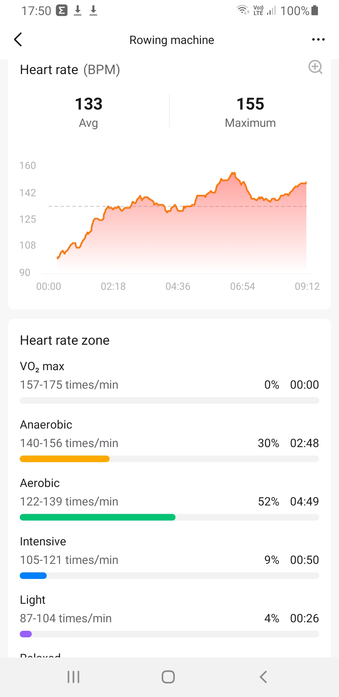
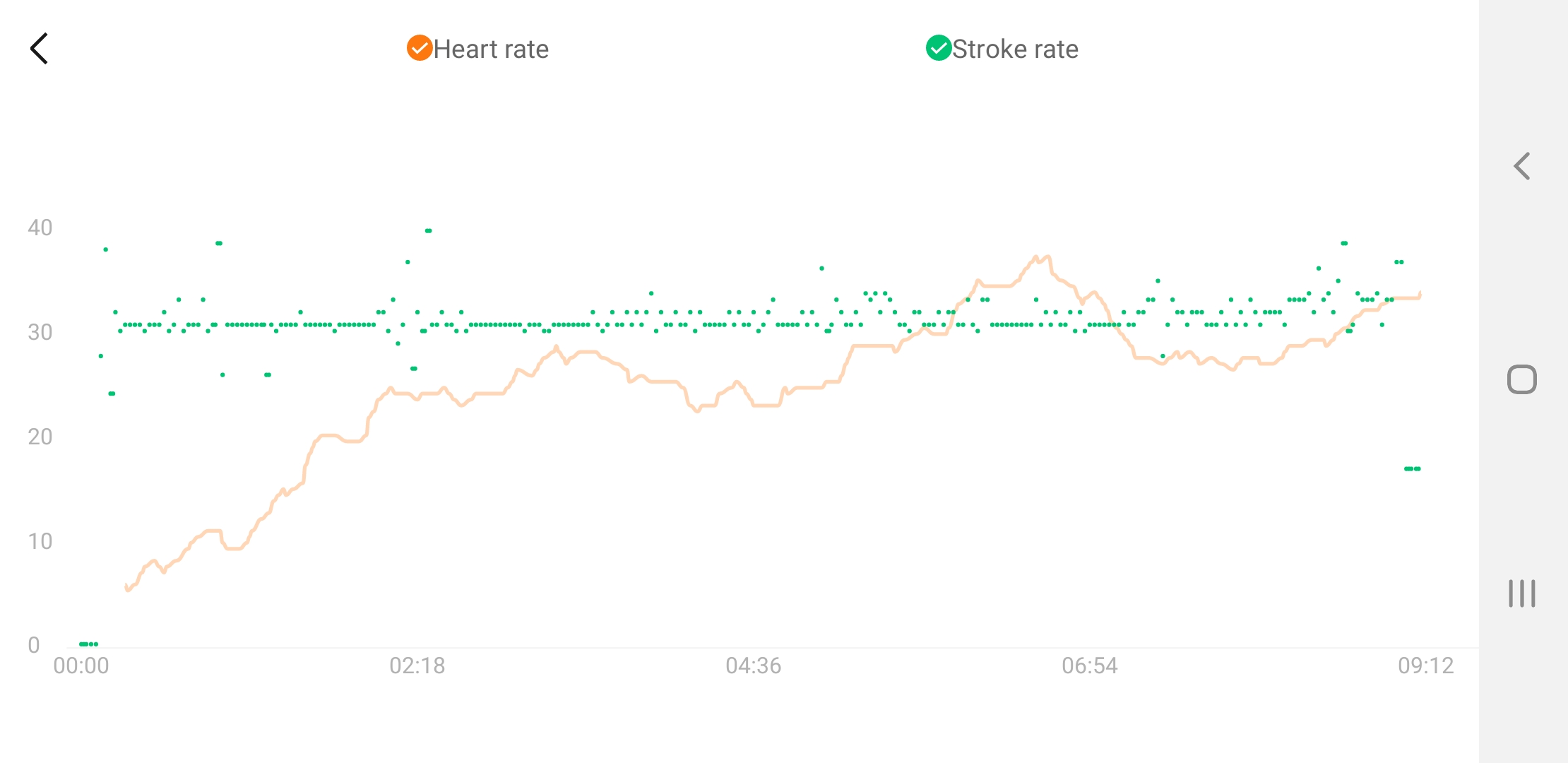
Key metrics missing from health monitoring include Blood Pressure (distinct from heartrate), breathing (respiration) rate and body temperature. Isn’t stress level dependent on these as inputs for meaningful recording?

Two minor issues, touch screen doesnt work correctly in water (swim activity should be triggered at poolside) and strap button can fly away when clipping / unclipping band, so care must be taken when removing band after swimming before entering Sauna / Steam Room (5 ATM waterproof rating excludes Spa use).

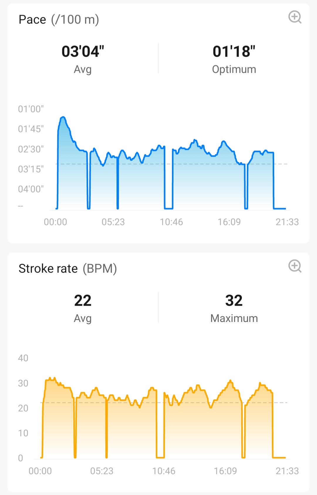
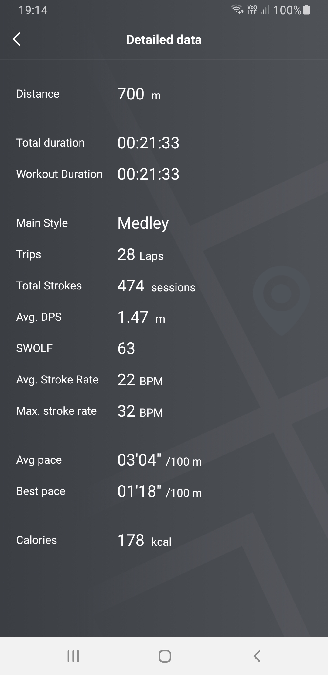
Swim tracking based on an indoor pool session is impressive, there is no need to enter pool length and distance, stroke rate and stroke classification appear accurate although Mi Fit does not display lap by lap breakdown.

For Gala’s or group training being able to contaclessly register participants bands with coach or club app would allow consolidation of timing and training data.

Also a lap timing stopwatch feature would be nice to have.

To record body weight (a key goal of most fitness programs) by default weight is manually input into Mi Fit.

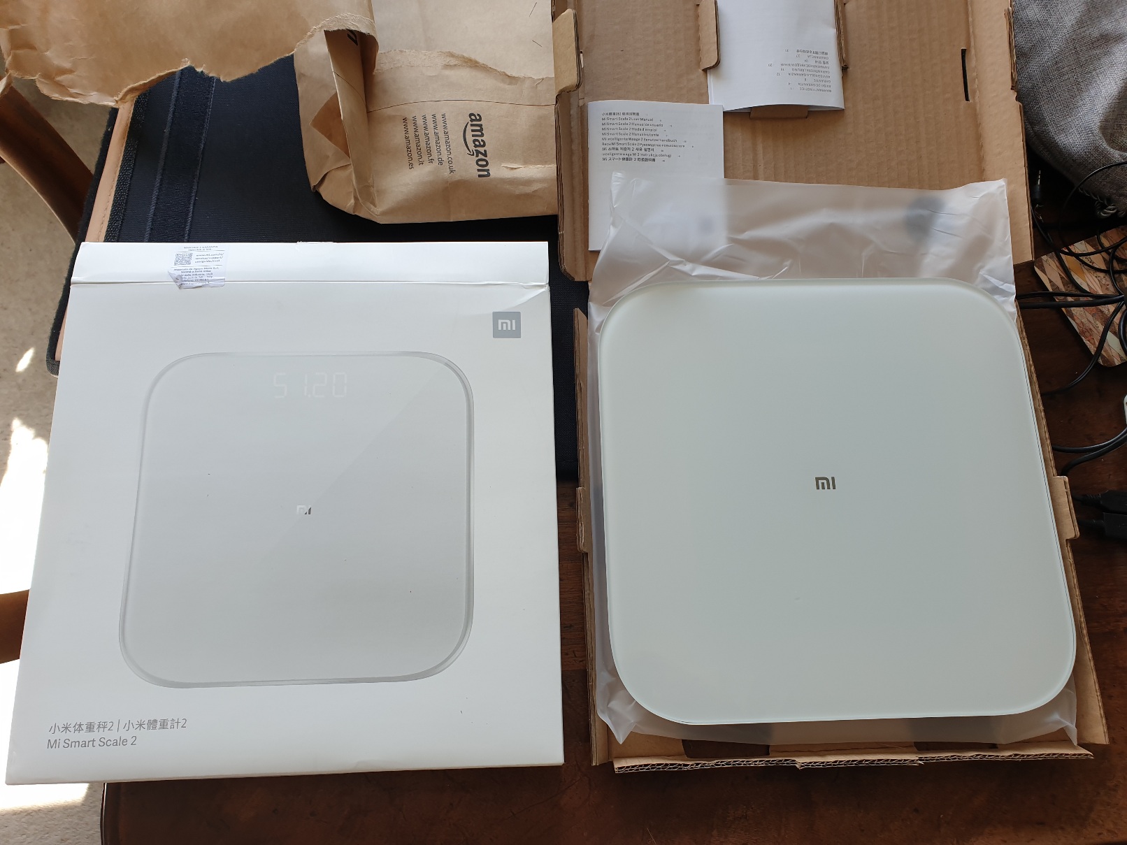
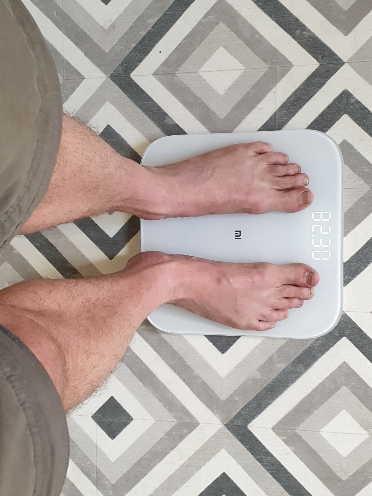
Enter Xiaomi smart scales, a wireless Bluetooth enabled companion device designed (and found in practise) to sync simply and seamlessly with Mi Fit.

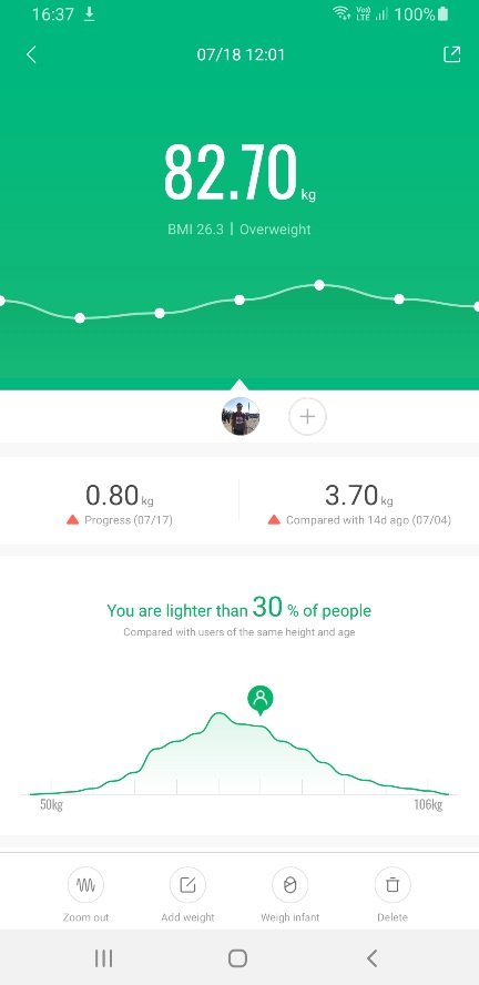
Mi Fit should allow users to set goals for weight loss (or gain) and show comparison to previous week / month / year.

Presently (Mi Fit v6 2.1) there doesn’t appear to be option to sync weight data to Mi Band 6.

Getting supplementary data into Mi Fit from other 3rd external sources, event timing systems, gym machines etc on completing a workout should be as easy as requesting / agreeing a Bluetooth data sync request.

Sadly no Life Fitness machines at local gym presently support Bluetooth and its not clear if Google Fit, Mi Fit or Strava have yet established an open standard interoperable and compatible with all bands, smartwatches and machine makers.

Motion sensor based activity auto detection: gesture recognition, counting and timing is not arguably without inaccuracies.

Considering underlying math complexity, long device battery life and low price point recognition of simple activities like rowing machine worked well. Yoga poses on other hand were not recognised in current version.

Behaviour Tagging feature suggests use of cutting edge AI Machine Learning – where user trains band for specific activity recognition / classification, resulting in personalised model and great accuracy for swim stroke or tennis shot recognition.

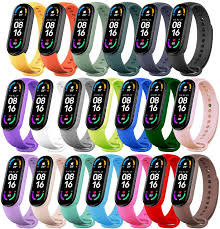
Overall Mi Band 6 has a winning low price point, impressive feature set, relatively good precision / tracking accuracy, brilliant sharp and bright OLED display and long battery life. Setup and sync with Mi Fit app and Xiaomi smart scales was simple and easy. Mi Fit dashboard app provides detailed and attractive graphical chart metrics. Finally, for fashion concious there’s a choice of inexpensive coloured and stylised replacement straps.

Xioami Mi Band 6 : from 2022 review of best waterproof swim fitness trackers:

https://www.coachmag.co.uk/fitness-trackers/6139/the-best-waterproof-fitness-trackers-for-swimmers

Categories
arduino C/C++ circuits Coding Embedded esp32 expressif Internet of Things microcontrollers MQTT sensors weather station WebSockets

SparkFun Weather Sensor Kit

Wind and Rain sensor kit newly arrived from SparkFun Electronics to upgrade an Arduino Weather Station project.

SparkFun Weather Sensor Kit, DIY prototypes, Arduino Weather Station

Also pictured are earlier DIY prototypes – a childrens bee wind spinner with hall effect sensor to count rotations, an anemometer made from recycled plastic packaging utilising a IR Led optical rotary encoder and a wind vane with eight fixed directional magnetic switches.

( more here: http://www.steveio.com/2020/07/21/weather-station-wind-vane-history-science/ and http://www.steveio.com/2020/07/21/weather-vane-hall-sensor-magnetic-rotary-encoder/ ).

Bee Windmill Anemometer with ESP32 LoRa Transmitter running on single 3.3v Li-Ion cell.
8 Durection WInd Vane with magnetic hall sensor array and WebSocket TCP web browser interface.
ESP8266 Anemometer with optical IR Led sensor, wifi connectivity and D3.js websocket provisioned UI.

( Code for these projects can be found on GitHib. )

Weather station projects are a popular accessible introduction to microelectronics; a microcontroller and sensors can be found at low cost, modular hardware design results in easy assembly and open software platforms like Arduino IDE streamline packaging and deployment of code to devices.

Analysing real time or historical time series data, from weather sensors is a lot of fun. Frameworks like R Project for Math Stats: https://www.r-project.org/ ) and Python, Pandas, Numpy & Mathplotlib provide implementations of most alogirithms and convenient data structures for importing & manipulating data.

Techniques and methods are transferable and can be applied to other domains or ontologies – finanicial, accounting data for example.

SparkFun offer an OEM Wind & Rain sensor kit manufactured by Shenzen Fine Offset Electronics, China.

With advent of 3d modelling & printing it is also feasible for an enthusiast to design and fabricate via a 3d printer custom sensor components, perhaps using template models downloaded from repos like ThingiVerse.

In competition marine OpenWind are defining what smart network connected sensors can achieve utilising Bluetooth LE to make near real time wind data available on smartphone.

Assembled SparkFun Weather Sensor Kit

Ideal for enthusiast or educator SparkFun Weather kit comes wihout circuitry,  microcontroller or software.  An add-on PCB designed for use with  Arduino / ESP32 can be purchased or Datasheet Technical Specs provide reference sensor circuit designs, not significantly complex due to use of magnetic reed switch and variable resistance technology.

MCU Sensor Control & Relay Unit – IP67 Weather Proof Enclosure, ESP32 TTGO LoRa microcontroller, light, temperature and air pressure sensors.

Traditionally 433MHz RF has been used for base station to transmitter devices. A popular project is to use Arduino, a cheap 433Mhz receiver and a library to read data from a commercial weather station designed for use with manufacturers display, enabling this data to be provisioned to the cloud.

For data transmission non GPRS (cellular) options include Bluetooth LE (range ~100 metres) or LoRa (Long Range Low Power Network – range between 300 – 10km depending on antenae) offering cableless wireless connectivity allowing remote sensor situation with no associated network costs.

At data layer WebSockets and MQTT for IOT devices are challenging serial protocols as defacto lightweight, reliable & easy to implement transport relays.

Apart from range and connectivity goals of low power consumption for efficient and long battery running time combined with solar charging enable devices to run standalone for long periods.

Is a single 3.3v Li-Ion Battery Cell Sufficient? TP405 Charging Module & Solar Panel

Weather Stations have applications beyond meteorology in smart agriculture, industrial, safety monitoring and for wind or wave based leisure pursuits. 

Assembling DIY Arduino Mega Weather Station v1.0

More generally Internet of things wireless networked smart sensor platforms can be used for many purposes and combined with AI and Machine Learning algorithms useful insight and patterns within data can be analysed, classified and predicted. 

SparkFun Smart ETextiles & Conductive Thread Kit

Personally, I really enjoyed SparkFun Arduino LilyPad e-textile, smart fabrics and conductive thread kit, so looking forward to now spinning up the Weather Station sensors!

Categories
circuits Internet of Things microcontrollers sensors Software weather station

Weather Station Wind Vane

What types of sensor can be used for a weather vane? How to track angular position using a rotary encoder? How easy is calibration? What coding considerations for a weather station wind direction project?

Mesopotamian base-60 number system resulted in our idea of 360° in a full circle. Early compasses described 32 points and eight cardinal directions of wind, serving as navigational aids for maritime exploration.

References recorded in ancient China as early as 139 BC described “wind observing fan”. In classical Greece astronomer Andronicus constructed a weather vane at “tower of winds” in Athens. Weather vanes were known in many places of antiquity.

The word “vane” derives from Old English “fane” (Germanic Fahne) signifying “cloth, banner, flag” all of which can be deployed as visual wind direction indicators.

In modern times, absolute and incremental encoders are sensor devices measuring rotary position (angle) and motion. Resolution, precision and accuracy have distinct meaning.

Absolute encoders maintain position during power off or device reset. Incremental motion encoder data is relative, sensors of this type require “homing” (passing a known position) to calibrate.

Lets consider some types of rotary encoder

  • magnetic rotary encoder
  • 360° Potentiometer
  • optical encoder
  • magnetic sensor array

Magnetic Rotary Encoder

Contactless magnetic encoders track a dipole magnet attached to a rotating shaft above sensor, recording rotational angle and direction through a full turn of 360° with high resolution and precision.

Internally hall sensors measure angular position of a magnetic field presented at surface, converting this to a voltage.

On chip digital signal processing (DSP) amplifies and filters planar field data before conversion by Analogue to Digital conversion (ADC).

Having no mechanical friction leads to long expected life span.

A wide operating temperature range (-40 Deg.C to 150 Deg.C) and environmental tolerances (~80% humidity) allow for a wide potential application range.

2/3 wire I2C/SPI programmable interfaces provide standardised micro-controller connectivity and control.

AS5600 Datasheet
MLX90316 Datasheet

Potentiometer 360 degree

Several commercial wind vanes targeted at maritime applications deploy a 360° potentiometer connected directly to vane shaft.

Having a compact, space efficient design, high resolution (degrees of direction) can be tracked.

Detent (stops or clicks) add rotational resistance and a fixed set of positions but increase friction.

Electro-mechanical contacts are subject to mechanical wear and surface corrosion of contact track impacting accuracy, durability and longevity.

Optical Encoder

Optical incremental encoders – IR LED / Sensor pair with a spinning disk interrupter are accurate at very high RPM rates with low sensor latency (rise time).

Resolution is determined by interrupt light “chopper” disk design and relative position is measured by counting rotational sensor ticks.

Quadrature or two channel encoding, with a phase offset, is employed to determine rotational direction.

Calibration, including between device reset/power off is a challenge – sensor pulse counting during rotation must be relative to a fixed/known initial position.

Magnetic Sensor Array

Early compasses recorded 32 points to indicate winds as a navigational aid to sailors.

Wiring 32 sensors together requires considerable soldering & assembly skill. If 4 or 8 bit resolution is sufficient, magnetic linear hall or reed switches might be used – both are contactless, low cost and widely available.

Sensors arranged in a ring array activated by a rotating magnet allow a micro-controller to track position changes.

One approach is to use polling and a GPIO pin per sensor. Pin change interrupts can also be used for state notification.

An analogue multiplexer (CD4051) reduces number of required input pins to 4 (3 address pins, 1 data), optionally a common interrupt enables this to work with an event (interrupt) driven model.

Sensor Implementation – Polling vs Event Model

Polling, reading position at a set frequency (interval), provides consistency and allows simple computation analysis – roll-up averages for example. Higher frequency sampling results in higher precision.

In event model – an interrupt is triggered when sensor state (position) changes.

Recording position data only when direction changes is a low power consumption approach, extending operating duration of a battery powered device, especially on windless days.

To implement event driven design with a multiplexer poses a challenge, at circuit level a common interrupt line wired with isolating diodes to each sensor is required.

A change to any individual sensor triggers an interrupt, micro-controller can then check each multiplexer channel to determine position.

Calibration – how to determine magnetic north?

A compass bearing is required to determine direction relative to cardinal directions.

Wind vanes in a fixed position are manually calibrated. Electronic sensor devices can resolve orientation relative to magnetic compass.

Wind direction is defined by World Geodetic System (WGS) as direction from which wind blows and is measured clockwise from geographical north, namely, true north (meteorology) or in aviation reporting relative to magentic north. 

Visualisation – Wind Rose and Polar Distribution Charts

Wind roses, a type of polar bar chart provide a visualisation of wind distribution: direction and magnitude (velocity) frequency at a location over a given time interval.

Categories
arduino circuits Coding Internet of Things microcontrollers sensors Software

Weather Vane – Magnetic Sensor Rotary Encoder

A ring of 8 magnetic digital hall sensors (one per cardinal direction) are activated by a rotating neodymium magnet attached to a shaft, creating a simple rotary encoder.

Hall Effect Magnetic Sensor array connected to Arduino UNO microcontroller.

Input Pull-Up Resistors

Each hall effect sensor is wired to a digital micro-controller pin.

To prevent “floating”, input pin state is biased HIGH using pull-up resistors .

External pull-up 10k resistors are connected between hall effect sensor 5v+ and digital out pins.

If no external resistors are present GPIO pins should be setup as INPUT_PULLUP activating microcontroller internal 20k pull up resistor.

Polling for Active Pin

Each iteration of loop() reads input pins to determine active sensor.

// current and previous active sensor pin
int active = NULL;
int lastActive = NULL;

void loop() {

  int v;
  active = 0;

  for(int i = 3; i <= 10; i++)
  {
    v = digitalRead(i);

    if (v == 0)
    {
      active = i;
    }
  }
  if (active == 0) // magnet between sensor positions
  {
      active = lastActive;      
  }
  if (active != lastActive)
  {
    Serial.print(active);
    Serial.print("\t");
    Serial.println(directionLabel[active-3]);
  }

  lastActive = active;
}

Variables are maintained to track current and previous activation, direction is updated on position change.

If magnet is between sensor positions and no pin is active, last active position is reported.

Compass Direction Labels

Finally pin number is translated to direction (“N”, “NE”, “E” etc) by indexing into an ordered character pointer array.

// pin order direction labels
char d0[] = "NE";
char d1[] = "SE";
char d2[] = "E";
char d3[] = "S";
char d4[] = "N";
char d5[] = "W";
char d6[] = "NW";
char d7[] = "SW";

char * directionLabel[] = { d0, d1, d2, d3, d4, d5, d6, d7 };

...
// i == active sensor pin number 3 - 10 
Serial.println(directionLabel[i-3]);

Interrupts – Event Driven

Instead of polling (reading sensors on each loop() iteration) we can minimise processing and power consumption by updating direction only when magnet position changes.

Less power is consumed reading current position from a variable in flash memory compared to reading each sensor input pin – decoupling logic to maintain position from code reporting current value increases efficiency.

On Arduino (Uno, Nano etc) by default specific pins trigger external interrupts. Any GPIO pin can be used as an interrupt trigger with pin change interrupts.

To setup pin-change interrupts for digital pins 3 – 10 :

volatile int irqState = 0;
unsigned long lastIrq;
int irqDelay = 100; // millisecs

ISR (PCINT0_vect) 
{
  irqState = 1; 
}

ISR(PCINT2_vect)
{
  irqState = 1; 
}

void setupPinChangeInterrupt()
{
  cli();

  // 1 – Turn on Pin Change Interrupts
  PCICR |= 0b00000001;      // turn on port b (PCINT0 – PCINT7) pins D8 - D13
  PCICR |= 0b00000100;      // turn on port d (PCINT16 – PCINT23) pins D0 - D7

  // 2 – Choose Which Pins to Interrupt ( 3 mask registers correspond to 3 INT ports )
  PCMSK0 |= 0b00000111;    // turn on pins D8,D9,D10
  PCMSK2 |= 0b11111000;    // turn on pins D3 - D7 (PCINT19 - 23)

  sei();                     // turn on interrupts
}

A full example of setting up Arduino pin change interrupts, checking state and reading pins from data register can be found on github and there’s a useful guide here.

Now in loop() we can check for active pin only when interrupt event occurs, software de-bounce timeout prevents multiple repeat activations:

void loop() {

  if (irqState == 1 &amp;&amp; (millis() - lastIrq > irqDelay))
  {

    // check for active pin...

    lastIrq = millis();
    irqState = 0;
  }
}

Hardware Common Interrupt

A more portable solution can be implemented in hardware by adding a common interrupt line from each Hall Sensor input, isolating switch input with a diode which conducts only in one direction.

Now a change to any sensor input causes common interrupt (pin D2) to go LOW, signalling to micro-controller to check and update active magnet position.

1N4148 High Speed Signal Diode isolate common interrupt line

A single external interrupt can be handled by Arduino Uno/Nano pin D2

attachInterrupt(0, pin2IRQ, FALLING);

Power consumption can be reduced further by implementing deep sleep between sensor change interrupts, waking only to update state or transmit position data at intervals.

Arduino Nano v3 micro-controller tracking interrupt triggered magnetic switch position

Real Time Wind Compass Web Interface

D3.js Wind Compass UI has a design inspired by Dieter Rams who worked for Braun and is single HTML file adapted from a simple clock.

Units range is changed to 360 divided into sub-divisions of 10 and 45 (8 compass directions).

User Interface (UI) Data Provisioning

A finished product might transmit data wirelessly using LORA, Wifi, Bluetooth or 433mhz RF.

For prototype testing we can use serialToWebsocket.py a script based on Python’s PySerial library to capture serial console output and relay this to a websocket.

python3 serialToWebsocket.py 
connected to: /dev/ttyUSB0

3	S
5	SW
4	W
6	NW

We can use Python to run a simple webserver to develop and test our interface –

python -m SimpleHTTPServer 3001

Wind Compass can now be loaded in a browser –

http://127.0.0.1:3001/wsWindCompass.html

UI demo and source code can be found below –

See it in action –

Full source code can on github:

Arduino Wind Vane Sketch:
https://github.com/steveio/arduino/tree/master/WindVane8HallSensor
Wind Compass D3.js Web UI:
https://github.com/steveio/mqttWebSocket/blob/master/wsWindCompass.html
Serial to Websocket Python Script
https://github.com/steveio/arduino/blob/master/python/serialToWebsocket.py