Categories
arduino C/C++ Coding Embedded esp32 esp8266 Internet of Things microcontrollers Software

Timed Device – Simple & lightweight scheduling for on/off devices

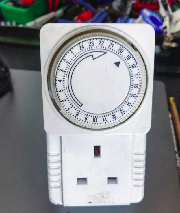
Timed Device is a library for Arduino / ESP 8266/32 embedded platforms written to emulate a simple plug in timer for an electrical device, where pins in a ring are set to define hour/minute status. Designed to be simple and lightweight optimisation is for low memory.

Arduino ATMega328 and related embedded microcontrollers provide internal high precision clock based timers suitable for events with second, millisecond and fine granularity (to clock speed 8 / 16 mhz).

When lower precision is sufficient, recurring timers for example where an event should occur on a specific minute, hour or day of week, a lightweight implementation can be achieved and storage for internal data structures can be optimised, a significant win factor on embedded systems where memory use is constrained.

The library follows an object orientated design pattern resulting in an extensible, scale-able architecture suitable for controlling from one to a large number of devices sharing a common timing core with each timed device class able to implement specific instructions for switching on/off.

Example use cases:

  • Switch lights or any electrical relay device on/off
  • Activate a pump or valve
  • Open/Close blinds, curtains or shutters
  • Control a fan, heat source or air conditioning

How to Define Time

In C time.h the tm structure has the following definition −

struct tm {
   int tm_sec;         /* seconds,  range 0 to 59          */
   int tm_min;         /* minutes, range 0 to 59           */
   int tm_hour;        /* hours, range 0 to 23             */
   int tm_mday;        /* day of the month, range 1 to 31  */
   int tm_mon;         /* month, range 0 to 11             */
   int tm_year;        /* The number of years since 1900   */
   int tm_wday;        /* day of the week, range 0 to 6    */
   int tm_yday;        /* day in the year, range 0 to 365  */
   int tm_isdst;       /* daylight saving time             */
};

While this structure is useful for point in time defined events, in case of a recurring timers this can be simplified.

If hour precision is sufficient, a single 32 bit mask can be used:

// Bitmask defines hours (from 24h hours) device is on (1) or off (0)
// 0b 00000000 23 22 21 20 19 18 17 16 15 14 13 12 11 10 9 8 7 6 5 4 3 2 1 0
long hourTimerBitmask =0b00000000001111111111111111100000;

Day of week (bit index 0 = Sunday – 6 Saturday) can be defined similarly:

long dayOfWeekTimerBitmask = 0b0101010;

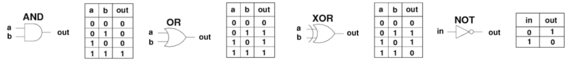
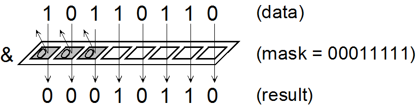
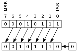
With bitmasks we can determine if an event is scheduled using bit shifts:

// Check if bit at pos n is set in 32bit long l
bool Timer::_checkBitSet(int n, long * l)
{
  bool b = (*l >> (long) n) & 1U;
  return b;
}

To check if an hour timer bitmask is on/off for 7am:

bool isSet = _checkBitSet(7, hourTimerBitmask)

For a more detailed guide to Bitmasks, shifts and bitwise operations see this article.

An on / off time occuring at specific (hour:minute) intervals can be defined as:

typedef struct tmElements_t {
  uint8_t Min;
  uint8_t Hour;
};

We can use a struct as container for an array of 1..n pairs of on/off times occurring on specified weekdays:

#define SZ_TIME_ELEMENT 2

typedef struct tmElementArray_t {
  unsigned long Wday;   // bitmap - days of week (bit index 0 = Sun - 6 Sat)
  struct tmElements_t onTime[SZ_TIME_ELEMENT];
  struct tmElements_t offTime[SZ_TIME_ELEMENT];
};

With these data structures we can setup up a pair of on/off times (08:00 -> 08:10 and 19:00 -> 19:30) to occur on Sun, Mon, Thur, Fri:

// create variables to define on/off time pairs
struct tmElements_t t1_on, t1_off, t2_on, t2_off, t3_on, t3_off;
struct tmElementArray_t timeArray;

t1_on.Hour = 8;
t1_on.Min = 0;
t1_off.Hour = 8;
t1_off.Min = 10;

t2_on.Hour = 19;
t2_on.Min = 0;
t2_off.Hour = 19;
t2_off.Min = 30;

timeArray.n = 2; // number of time pairs
timeArray.Wday = 0b00110011; // define days of week timer is active on

timeArray.onTime[0] = t1_on;
timeArray.offTime[0] = t1_off;

Check if a recurring timer is set

How we check a timer (whether bitmask or time based) depends on the type of time source we have.

Most familiar time source on Arduino is millis() function providing elapsed time in milliseconds since device reset / startup.

This is useful for timing events in a non-blocking way at recurring intervals:

if (millis() >= sampleTimer + sampleInterval)
{
  ... do something
  sampleTimer = millis();
}

But what if we want to schedule in terms of hour, minute or day of week based on current time?

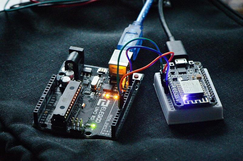
To achieve this a micrcontroller is combined with a Real Time Clock module, providing a battery backed time source that once synced (for example to an NTP time source) maintains current time even when device is switched off.

Arduino Nano in pin breakout board with DS3231 Real Time Clock Module

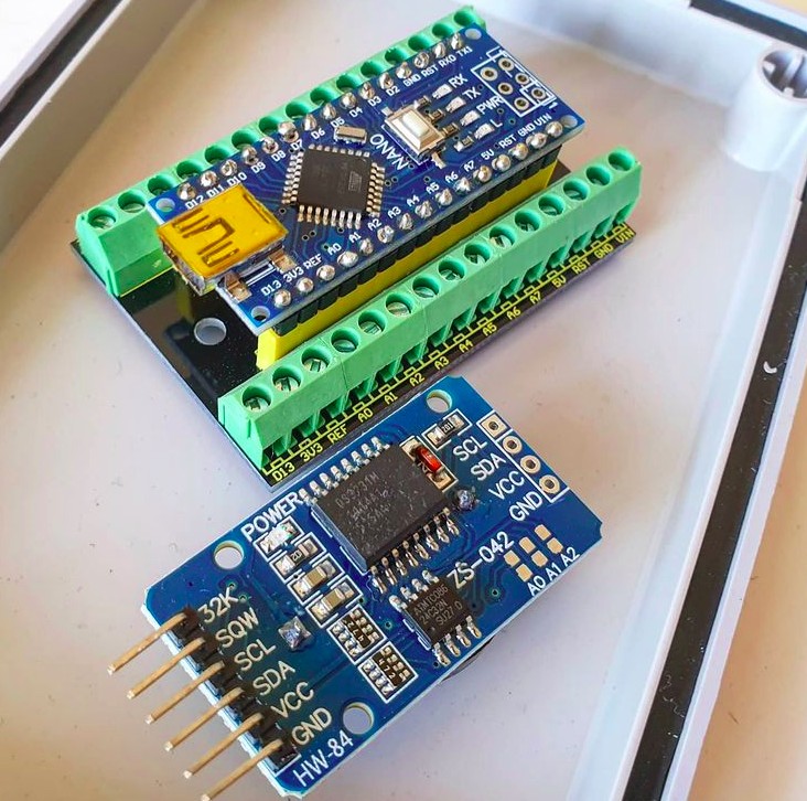
Arduino DS1307/3231 RTC modules have supporting libraries (for example RTCLib from Adafruit) to obtain current time usually in form of:

DateTime now = rtc.now();

Where DateTime object provides an API to return specific time elements:

Serial.print(now.hour());
Serial.print(':');
Serial.println(now.minute());
Serial.print(now.dayOfTheWeek());

Is an event scheduled (at a specific point in time)?

In C function overloading can be used to provide multiple interfaces to an isScheduled() method according to timer precision / time source type :

bool isScheduled(int h);
bool isScheduled(int h, int d);
bool isScheduled(int m, int h, int d);
bool isScheduled(unsigned long ts);

(Where h = hour, m = minute, d = week day)

Most users of Unix based systems are familiar with “timestamp” a 32bit unsigned long representing elapsed seconds since a fixed point in time, the Unix Epoch which occurred 1970-01-01 00:00:00 UTC.

Unix is not unique in using a reference Epoch, they have been used in calender systems worldwide since ancient times.

We can obtain current timestamp on Linux via command line with date command:

stevee@ideapad-530S:~$ date +%s
1620155520

A timestamp as a time source can be used with any timer definition, whether point in time or recurring. It has advantage (compared to using numeric representations of individual time elements) that a single long number can be used for computation and conversion and we don’t need to worry about problems like variable number of days in month or leap years.

Timestamps and time and date conversion tricks

For a timer defining specific days of week, the first question might be how to obtain weekday from a unix timestamp (elapsed seconds since epoch)?

int weekday = (floor((ts / 86400)) + 4) % 7;

1970-01-01 was a Thursday, dividing timestamp by 86400 (number of seconds in a day: 24 * 60 * 60) gives number of days since epoch, adding 4 shifts start day to Sun and modulo 7 returns day of week.

To check if a timestamp is within range of one or more on/off time pairs (specified in hh:mm format as uint8_t Min; uint8_t Hour;) first we convert all time elements to elapsed seconds:

// convert fully qualified timestamp to elapsed secs from previous midnight
unsigned long elapsedTime = ts % SECS_PER_DAY;

unsigned long s1, s2, onTime, offTime;

// check each timeArray on/off pair
for (int i = 0; i < _timeArray->n; i++)
{
  s1 = _timeArray->onTime[i].Min * SECS_PER_MIN;
  s2 = _timeArray->onTime[i].Hour * SECS_PER_HOUR;
  onTime = s1 + s2;
  s1 = _timeArray->offTime[i].Min * SECS_PER_MIN;
  s2 = _timeArray->offTime[i].Hour * SECS_PER_HOUR;
  offTime = s1 + s2;

  if (elapsedTime >= onTime &amp;&amp; elapsedTime <= offTime)
  {
    return true;
  }
}

Conclusion

While TimedDevice library is non-blocking (it does not technique like delay()) it is not truely asynchronous or event driven as each device implementing a timer must poll for an event on each iteration of loop().

This could constrained to checking once per second/minute/hour but perhaps a better architecture would be to use either RTC DS3231 squarewave or Arduino internal timer to register and trigger an interrupt with an associated handler only when an event is due to occur.

Similarly if either a very large number of events are scheduled, or a large set of timed devices created, it would be sensible to register these with a scheduler (akin to a CPU scheduler) tasked with sorting, prioritising and actioning event queue in an efficient way, which might utilise a multi-threaded approach on multi-core CPU architectures.

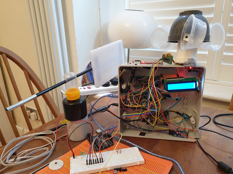
Source code for Timed Device library can be found on GitHub including a full Arduino sketch example for defining a solenoid valve timer with an RTC timesource.

Categories
arduino C/C++ Coding microcontrollers Software weather station

Sunrise / Sunset – Is Arduino ahead of Its Time?

Recently I added Sun Moon Library to my DIY Arduino Weather Station.

Given a location specified as Latitude / Longitude coordinates and a date / time this clever algorithm uses astronomical math routines to provide timing of sunrise, sunset and moon age.

https://www.flickr.com/photos/jannerboy62/31589567761/

In spite of Arduino ATMega328p chipset being only an 8 bit architecture and float data type being low precision ( 6 – 7 decimal digits ) timings output by sun moon are said to be accurate to second scale.

Comparing results with UK Met Office weather forecast during testing I found Arduino sunrise / sunset timings to be out, with a margin or error of around 15 minutes.

Being suspicious of data, one sunny afternoon I found a vantage point and watched sun disappear below horizon, timing the event.

Sure enough Arduino data was indeed inaccurate.

Arduino DIY Weather Station and sensors.

What could be the problem?

While my knowledge of maths is not sufficiently advanced to properly understand each line of Sun Moon library algorithm, to eliminate possibility of faulty code I decided to try another implementation, Dusk to Dawn.

After running a test for same location, result with new library continued to show an inaccuracy of 15 minutes.

Weather Station timing (date / time) is provided by a Real Time Clock (DS3132 module) which is synced from internet via Network Time Protocol (NTP). A quick check showed date and time to be correct, although manual correction for daylight savings time (DST) seemed sub-optimal.

This pointed to a coordinate error.

Google gives my location Bournemouth, UK as Longitude / Latitude 50.7192° N, 1.8808° W.

Google results for Latitude / Longitude Bournemouth, UK

These coordinates are defined in Weather Station code as:

// Lat/Long: Bournemouth 50.7192° N, 1.8808° W
#define LOC_latitude    50.7192
#define LOC_longtitude  1.8808

Here was the problem.

Checking cooordinates for another location, London, UK ( 51.5074° N, 0.1278° W ) Arduino gave sunrise / sunset with only a minor ( < 1 minute) difference in timing.

Bournemouth is West of Greenwich Meridian (zero line for Longitude) by approx 107 miles. Each degree of latitude is approximately 69 miles (111 kilometers) apart.

Google gives coordinates (50.7192° N, 1.8808° W) as decimal degrees and “N/S/E/W”, a human friendly representation.

Arduino code expects decimal degrees and Plus/minus symbol.

ISO 6709 International Standard defines Longitude as a number preceded by a sign character. A plus sign (+) denotes east longitude or the prime meridian, and a minus sign (-) denotes west longitude or 180° meridian (opposite of the prime meridian)

Similarly, according to Microsoft, “The latitude is preceded by a minus sign ( – ) if it is south of the equator (a positive number implies north)”.

Updating Weather Station to include latitude minus symbol, code now provided accurate timings –

// Lat/Long: Bournemouth 50.7192° N, 1.8808° W
#define LOC_latitude    50.7192
#define LOC_longtitude  -1.8808

In navigation, the 1 in 60 rule states that for each degree off (or displacement) over a distance of 60 nautical miles (NM), it will result in 1 NM off course

A trans Atlantic journey by boat from Southampton to New York ( 2974.5 nautical miles ), given a similar error in bearing of ~2 degrees might arrive in Boston or possibly Washington.

Sunrise / Sunset times on Arduino LCD Weather Station display

We were in agreement at last, today sunrise would occur at 06:25 and sunset at 19:46.

References:

https://github.com/steveio/arduino/blob/master/WeatherStation/WeatherStation.ino

https://en.wikipedia.org/wiki/ISO_6709#Longitude

https://docs.microsoft.com/en-us/previous-versions/mappoint/aa578799(v=msdn.10)?redirectedfrom=MSDN

https://stackoverflow.com/questions/51626412/getting-negative-values-of-latitude-and-longitude

https://www.metoffice.gov.uk/weather/forecast

Categories
C/C++ Coding Embedded microcontrollers Software

Binary – Bits, Bitwise Operators & Bitmasks

First we define bits, bit fields and bit masks, relating these to data structures, addressable memory storage, registers and binary protocol frames.

Bitwise logic is introduced with simple practical examples – bitwise operators and bit shifts – setting individual bits on or off, extracting bits for reading, manipulating bits or checking bit field values.

Bitwise Logic Gates

In Assembler, C and other programming languages bit manipulation is common especially when implementing low level hardware interfaces, embedded microcontroller based IOT devices, processing sensor, machine, network and peripheral data.

Graphics programming and image manipulation also utilises bitwise operations and bitmaps to perform animation (shifting and moving bits), compositing and pixel value modification.

Bits, Bytes & Bitmasks Explained

Bits are smallest unit of storage representing either a binary 1 or 0.

A byte is a group of binary digits or bits (typically eight) operated on as a unit.

Bit fields are a series or array of bits in adjacent memory.

Bit field values might represent a set of individual attributes (boolean on/off “flags” or status fields), a register value (storage address / instruction), or encapsulate binary encoded data.

AND bitmask

A bitmask (or mask) is an ordered set of bits of defined length used in bitwise logic to set, invert or manipulate another bit field.

Registers – Bit Arrays

Registers encapsulate a set of ordered bits in storage with a defined bit length typically expressed as power of base 2 (commonly 8 / 16 / 32 / 64 / 128 bit).

76543210
8 bit register where least significant bit (LSB) starts with (2º = 1)

An 8 bit register can hold unsigned (positive) numbers from 0 to 255 or signed (includes negative) values from -128 to +127 (where bit 7 is a sign bit).

Registers are used to address memory locations for computations within central processing unit, configuration parameters, IO from data storage, ports, or peripherals.

Bits in a Byte – Memory Address

Bitwise shift operators, along with logical AND can be used to access individual bits within a byte of memory for any variable in C.

To read value of bit at index 4 of an 8 bit length variable x

int x = 16; // 10000
printf("%d\n", (x >> 4) &amp; 0x01); // Prints 1

Network Protocols – Binary Bit Sequences

Bit sequences are used in network protocols where packetised messages are arranged into frames containing fields with defined offset and length.

A frame refers to the entire data packet which is being sent/received during a communication. Each protocol defines a specification of its own frame format.

An RS232 serial protocol frame defines a bit sequence –

Frame:StartDataParityStop
Size (bits):15-911-2
Bit sequence format of a USART serial protocol frame

Bitwise operators and shifts can be used to efficiently read, set or modify fields within a network protocol packet.

Bitwise Operators

Bitwise operations allow setting bit sequence values in a single operation and are more efficient than loops or maintaining individual bits.

SymbolOperator
&bitwise AND
|bitwise inclusive OR
^bitwise XOR (exclusive OR)
<<left shift
>>right shift
~bitwise NOT (one’s complement) (unary)
Bitwise and shift operators

Logical operators AND, OR, XOR (Exclusive OR) and NOT (Negation) implement bitwise manipulation, incurring a minimal number of processing instructions.

Comparing bit by bit –

  • OR sets a bit if one or both operators are true: 1110 OR 0000 = 1110
  • AND sets a bit if both operators are true: 1010 AND 1101 = 1000
  • AND with zero-check tests if any bit is set: 1010 AND 0010 = 0010 ≠ 0
  • XOR sets a bit if only one operator is true: 1010 XOR 0100 = 1110
  • NOT inverts all bits: NOT 1011 = 0100

Bitwise operators work on integer and character data types and do not modify value of their arguments so assignment (=, +=, -=, |=, &=) is typically used for example x |= (y & z).

Arithmetic Bit Shifts

Left Arithmetic Shift

Bit or Arithmetic shift operators << >> treat a value as a series of individual bits rather than a numerical quantity, shifting (or moving) bit positions left or right.

These operations are useful to move a bit or set of bits to a specific positional index.

In a left shift operation (<<) bits are moved by one position to the left and last digit is zero filled. This is equivalent to multiplication of a signed integer by a power of 2.

01101011
8 bit Binary encoding of decimal 107

Left shifting 2 bits ( << 2) results in

10101100
8 bit Binary encoding of decimal 172

A right shift operation (>>) moves bits right by a specified number of positions, dividing number by 2.

In more general form we can say –

// x multiplied by 2ⁿ
x << n
// x divided by 2ⁿ 
x >> N

Notes –

  • Bits shifted from end are lost due to overflow, they do not wrap around.
  • Right bitshift on signed types – gcc promises to always give the sane behavior (sign-bit-extension) but ISO C allows the implementation to zero-fill the upper bits.

Defining bit masks in C

Bitmasks are used in bit manipulation and combined with a logical operator (AND, OR XOR) define a pattern for bits to keep or discard.

In c++14 which supports binary literals bit masks are defined –

const uint8_t mask0 = 0b00000001 ; // represents bit 0
const uint8_t mask1 = 0b00000010 ; // represents bit 1
const uint8_t mask2 = 0b00000100 ; // represents bit 2
...  

Using Hexadecimal

const uint8_t mask0 = 0x01 ; // bit 0  0000 0001
const uint8_t mask1 = 0x02 ; // bit 1  0000 0010
const uint8_t mask2 = 0x03 ; // bit 2  0000 0100
...  

Or with bit shift operator

const uint8_t mask0 = 1 << 0 ; // 0000 0001
const uint8_t mask1 = 1 << 1 ; // 0000 0010
const uint8_t mask2 = 1 << 2 ; // 0000 0100
...

Set, Clear, Modify, Toggle & Check Bits

Set a bit
Set the nth bit ( zero up to n-1 ) of number

number |= 1UL << n

Set bit 0 of i to one

i |= 1 << 0;

// Example
000 i
001 1 << 0;
001 i |= 1 << 0;

  • the << operator is left “bit shift” operator which moves all bits to the left n times.
  • 1UL species numeric literal 1 with type Unsigned Long

Clear a bit
Set nth bit of number to zero

number &= ~(1UL << n);

Set bit 1 of i to zero

i &= ~(1UL << 1);

// Example
010 i
000 ~(1UL << 1)
000 i &= ~(1UL << 1);
  • ~ negates value of bit 1 from 1 to 0
  • AND evaulates false as both operands are not equal

Toggle (flip) a bit

Toggle nth bit of number

number ^= 1UL << n;

Toggle (flip) bit 0 of i

i ^= 1 << 0;

// Example
001 i
001 1 << 0
000 i ^= 1 << 0
  • ^= represents XOR exclusive OR with assignment, output is true when operand bits are different

Check a bit is set

True if nth bit of number equals 1

bit = (number >> n) & 1U;

Check bit 7 of i assign 1 or 0 to bit

int bit = (i >> 7) & 1U;

Modify – Changing a bit to x (1 or 0)

// 2s complement system with negation behaviour
number ^= (-x ^ number) & (1UL << n); 
// portable
number = (number & ~(1UL << n)) | (x << n);

Set bit 7 of i to x

i ^= (-x ^ i) & (1UL << 7);
i = (i & ~(1UL << 7)) | (x << 7);

Notes –

  • range / bounds checking is not applied, out of bounds shift index result in undefined behaviour
  • Use 1ULL if number is wider than unsigned long
  • endianess (position of most / least significant bit) and signing varies between platforms and compilers

Bitwise Functions as C Pre-Processor Macros

To minimise code duplication bit operator functions can be defined in a header file as pre-processor macros

/* a=number, b=bit index 0-n */
#define BIT_SET(a,b) ((a) |= (1UL<<(b)))
#define BIT_CLEAR(a,b) ((a) &amp;= ~(1UL<<(b)))
#define BIT_FLIP(a,b) ((a) ^= (1UL<<(b)))
#define BIT_CHECK(a,b) (!!((a) &amp; (1UL<<(b))))

Print Bits in C as Left Padded Binary String

In C printf() does not have a format specifier to print a string representation of binary, but we can write a function to achieve this –

const unsigned bits = 8;

// print integer value as a left padded binary string
void print_bits(unsigned value)
{
    unsigned mask = 1 << (bits-1);

    while (mask)
    {
        printf("%d", (mask &amp; value) != 0);
        mask >>= 1;
    }

    printf("\n");
}

int main()
{
  int i = 0x145;
  print_bits(i);
}

Result:
01000101

References and Further Reading:

[1] Methods for Bit Manipulation & Discussion:
https://stackoverflow.com/questions/47981/how-do-you-set-clear-and-toggle-a-single-bit/263738#263738

[2] Theory and examples of Bitwise Operation:
https://en.wikipedia.org/wiki/Bitwise_operation

[3] Bit Twiddling Hacks – Advanced Bitwise Algorithms http://graphics.stanford.edu/~seander/bithacks.html

Categories
arduino C/C++ esp8266 Internet of Things Python Software WebSockets

WebSocket Binary – ESP8266 to Web Browser

Binary wire protocols are long established for embedded machine to machine (M2M) communication, network applications and wireless radio data transmission.

Internet of Things (IOT) devices, real time sensors, robotics, smart home of industrial machine control data also demand efficient, low latency & lightweight data communications.

WebSockets ( RFC6455 ) protocol brings native support for binary framed messaging to web browser clients, offering a compact lightweight format for fast and efficient endpoint messaging.

Why use binary format data messaging?

Compared to serialisation of more complex text based wire formats, binary is lightweight and requires minimal storage / bandwidth and processing.

Taking an example key/value command data message:

// JSON encoding
{"cmd":101,"value":180}
23 * 2 = 46 bytes

// CSV plain text encoding
101,180\n
9 * 2 = 18 bytes 

// Binary
101 180
int (4 bytes) + int(4 bytes)
4+4 = 8 bytes

In case of high performance applications supporting a large number of clients or very high frequency of data exchange, minimising data size, bandwidth and processing becomes an important priority.

Binary wire protocols are long established for embedded M2M messaging

Taking as a simple example an embedded ESP8266 WiFi device, message gateway and web browser client, data serialisation and bidirectional binary framed WebSocket data exchange are demonstrated.

ESP8266 Byte Array Serialisation

Internally data is represented in embedded microcontrollers as ones and zeros, sequences of bits arranged in addressable memory.

Higher level programming language abstraction provides human readable textual labels and in case of C/C++ associated type information.

Lets define a mixed type data structure that could be some kind of sensor or message data payload –

    // define mixed type data struct
    struct Data
    {
        int id;
        float v1;
        float v2;
        unsigned long v3;
        char v4[20];
    };

    struct Data data;

    // populate data values
    data.id = 67;
    data.v1 = 3.14157;
    data.v2 = -7.123;

    unsigned long ts = millis();
    data.v3 = ts;

    char c[20] = "N NE E SE S SW W NW";
    strncpy(data.v4, c, 20);

To access underlying bytes, a pointer to data structure address is created –

    uint8_t * bytePtr = (uint8_t*) &data;    
    webSocket.sendBIN(bytePtr, sizeof(data));

Data pointer and length are passed to WebSocket send method “webSocket.sendBIN()”, byte range is read, packaged (framed) according to protocol specification and written to TCP/IP network socket.

Hexidecimal and Binary text representation of in memory data structure can also be displayed –

void printBytes(const void *object, size_t size)
{
    const uint8_t * byte;
    for ( byte = (uint8_t *) object; size--; ++byte )
    {
        Serial.print(*byte, HEX);
        Serial.print("\t");
        Serial.println(*byte, BIN);
    }
    Serial.println('\n');
}

Python WebSocket Server

A Python3 middleware hosts WebSocket server and acts as a message relay gateway.

Binary WebSocket messages can be decoded in Python, the struct module performs conversions between Python data types and C structs –

async def wsApi(websocket, path):
    try:
        async for message in websocket:
            print('User-Agent: '+ websocket.request_headers['User-Agent'])
            print('Sec-WebSocket-Key: '+websocket.request_headers['Sec-WebSocket-Key'])
            print('MessageType: '+str(type(message)))
            print(message);
            print('Hex: '+message.hex());

            if isinstance(message, (bytes, bytearray)):

                i = message[:4];
                print(i);
                tuple_of_data = struct.unpack("i", i)
                print(tuple_of_data)

                tuple_of_data = struct.unpack_from("f", message, 4)
                print(tuple_of_data)

                tuple_of_data = struct.unpack_from("f", message, 8)
                print(tuple_of_data)

                tuple_of_data = struct.unpack_from("i", message, 12)
                print(tuple_of_data)

                tuple_of_data = struct.unpack_from("20s", message, 16)
                print(tuple_of_data[0])

                ## forward message
                await asyncio.wait([user.send(message) for user in USERS])

To index into byte array and read a number of bytes according to data type being unpacked Python’s array slice method “i = message[:4]” can be used where [<from>:<to>] specifies start/end positions.

Method struct.unpack_from() is another approach, taking as parameters a format character specifying data type (“i” – integer, “f” – float), data buffer and an index (in bytes) to read from.

Here is decoded binary message output including some WebSocket headers –

User-Agent: arduino-WebSocket-Client
Sec-WebSocket-Key: zoJ0aR/5XunSvEKKcUkWfQ==
MessageType: <class 'bytes'>
b'C\x00\x00\x00|\x0fI@\x9e\xef\xe3\xc0\xb9\x17\x00\x00N NE E SE S SW W NW\x00'
Hex: 430000007c0f49409eefe3c0b91700004e204e45204520534520532053572057204e5700
b'C\x00\x00\x00'
(67,)
(3.1415700912475586,)
(-7.123000144958496,)
(6073,)
b'N NE E SE S SW W NW\x00'

Web Browser – Binary Encode/Decode in JavaScript

In web browser, JavaScript primitives Blob, ArrayBuffer and TypedArray perform a similar conversion.

Firstly, received WebSocket messages (event object) can be debugged to console –

 websocket.onmessage = function (event) {
    console.log(event);

Binary framed data payload is reported as type “Blob” (raw data) of length 36 bytes –

Chrome Developer Tools console log for WebSocket Binary message receieve event

To de-serialise message, raw data Blob is converted asynchronously using FileReader API to ArrayBuffer, a generic fixed length binary data buffer –

    if (event.data instanceof Blob)  // Binary Frame
    {
      // convert Blob to ArrayBuffer
      var arrayPromise = new Promise(function(resolve) {
          var reader = new FileReader();

          reader.onloadend = function() {
              resolve(reader.result);
          };

          reader.readAsArrayBuffer(event.data);
      });

When promise is fulfilled, ArrayBuffer can be read using typed views (Uint32Array, Uint32Array) for integer (including long) and float types, TextDecoder API is used to decode character array –

arrayPromise.then(function(buffer) {

          // Decoding Binary Packed Data

          // int (4 bytes)
          var arrInt = new Uint32Array(buffer);
          var id = arrInt[0];
          console.log("id:"+id);

          // 2x float (4 bytes)
          var arrFloat = new Uint32Array(buffer,4);
          var v1 = arrFloat[0];
          var v2 = arrFloat[1];
          console.log("v1: "+v1);
          console.log("v2: "+v2);

          // long (4 bytes)
          var v3 = arrInt[3];
          console.log("v3:"+v3);

          // character data (20 bytes)
          var uint8Array = new Uint8Array(buffer,16);
          var string = new TextDecoder("utf-8").decode(uint8Array);
          console.log(string);
      });

JavaScript Binary Data Encoding

Binary data can also be encoded from native JavaScript. TypedArrays created for each data type – integer, float, long and character array are populated and packed into an ArrayBuffer suitable for use as WebSocket data payload –

console.log("Binary Encode example");

// Binary Encode example
var buffer = new ArrayBuffer(36)
var arrInt =   new Uint32Array(buffer, 0, 1);
arrInt[0] = 67;
var arrFloat = new Float32Array(buffer, 4, 2);
arrFloat[0] = 3.14157;
arrFloat[1] = -7.123;

var arrInt2 =   new Uint32Array(buffer, 12, 1);
arrInt2[0] = Date.now();

var uint8Array = new Uint8Array(buffer,16);
var charBuffer = new TextEncoder("utf-8").encode("N NE E SE S SW W NW");

for(var i = 0; i<charBuffer.length; i++)
{
  uint8Array[i] = charBuffer[i];
}

// send binary data
websocket.send(buffer);

At message gateway, logs demonstrate parity between data packed by embedded device and those sent from web browser client –

User-Agent: Mozilla/5.0 (X11; Linux x86_64) AppleWebKit/537.36 (KHTML, like Gecko) Chrome/69.0.3497.100 Safari/537.36
Sec-WebSocket-Key: 1TD9Zp71cMTivUbj+QSx5w==
MessageType: <class 'bytes'>
b'C\x00\x00\x00|\x0fI@\x9e\xef\xe3\xc0\x07\x1c\xff\x91N NE E SE S SW W NW\x00'
Hex: 430000007c0f49409eefe3c0071cff914e204e45204520534520532053572057204e5700
b'C\x00\x00\x00'
(67,)
(3.1415700912475586,)
(-7.123000144958496,)
(-1845552121,)
b'N NE E SE S SW W NW\x00'

Limitations / Drawbacks

Compared to UTF-8 text formats (XML, JSON) packed binary data has significant disadvantages –

  • legibility – text based key/value formats are easy to read, manipulate and maintain
  • fixed frame boundaries – using positional byte sequence indexes means even small changes to message structure, size or field position require updates to consumer client code
  • endianess / alignment / padding must be maintained consistently, compiler and platform implementation differences may occur

Security

WebSockets Secure (WSS) offers transport layer security (TLS) to encrypt data streams. An authentication and authorisation strategy (challenge/response password, token or certificate based) for client identification should also be deployed. Cryptographic message digest signing or encryption might also be used as extra protection for critical data.

Categories
circuits Internet of Things microcontrollers sensors Software weather station

Weather Station Wind Vane

What types of sensor can be used for a weather vane? How to track angular position using a rotary encoder? How easy is calibration? What coding considerations for a weather station wind direction project?

Mesopotamian base-60 number system resulted in our idea of 360° in a full circle. Early compasses described 32 points and eight cardinal directions of wind, serving as navigational aids for maritime exploration.

References recorded in ancient China as early as 139 BC described “wind observing fan”. In classical Greece astronomer Andronicus constructed a weather vane at “tower of winds” in Athens. Weather vanes were known in many places of antiquity.

The word “vane” derives from Old English “fane” (Germanic Fahne) signifying “cloth, banner, flag” all of which can be deployed as visual wind direction indicators.

In modern times, absolute and incremental encoders are sensor devices measuring rotary position (angle) and motion. Resolution, precision and accuracy have distinct meaning.

Absolute encoders maintain position during power off or device reset. Incremental motion encoder data is relative, sensors of this type require “homing” (passing a known position) to calibrate.

Lets consider some types of rotary encoder

  • magnetic rotary encoder
  • 360° Potentiometer
  • optical encoder
  • magnetic sensor array

Magnetic Rotary Encoder

Contactless magnetic encoders track a dipole magnet attached to a rotating shaft above sensor, recording rotational angle and direction through a full turn of 360° with high resolution and precision.

Internally hall sensors measure angular position of a magnetic field presented at surface, converting this to a voltage.

On chip digital signal processing (DSP) amplifies and filters planar field data before conversion by Analogue to Digital conversion (ADC).

Having no mechanical friction leads to long expected life span.

A wide operating temperature range (-40 Deg.C to 150 Deg.C) and environmental tolerances (~80% humidity) allow for a wide potential application range.

2/3 wire I2C/SPI programmable interfaces provide standardised micro-controller connectivity and control.

AS5600 Datasheet
MLX90316 Datasheet

Potentiometer 360 degree

Several commercial wind vanes targeted at maritime applications deploy a 360° potentiometer connected directly to vane shaft.

Having a compact, space efficient design, high resolution (degrees of direction) can be tracked.

Detent (stops or clicks) add rotational resistance and a fixed set of positions but increase friction.

Electro-mechanical contacts are subject to mechanical wear and surface corrosion of contact track impacting accuracy, durability and longevity.

Optical Encoder

Optical incremental encoders – IR LED / Sensor pair with a spinning disk interrupter are accurate at very high RPM rates with low sensor latency (rise time).

Resolution is determined by interrupt light “chopper” disk design and relative position is measured by counting rotational sensor ticks.

Quadrature or two channel encoding, with a phase offset, is employed to determine rotational direction.

Calibration, including between device reset/power off is a challenge – sensor pulse counting during rotation must be relative to a fixed/known initial position.

Magnetic Sensor Array

Early compasses recorded 32 points to indicate winds as a navigational aid to sailors.

Wiring 32 sensors together requires considerable soldering & assembly skill. If 4 or 8 bit resolution is sufficient, magnetic linear hall or reed switches might be used – both are contactless, low cost and widely available.

Sensors arranged in a ring array activated by a rotating magnet allow a micro-controller to track position changes.

One approach is to use polling and a GPIO pin per sensor. Pin change interrupts can also be used for state notification.

An analogue multiplexer (CD4051) reduces number of required input pins to 4 (3 address pins, 1 data), optionally a common interrupt enables this to work with an event (interrupt) driven model.

Sensor Implementation – Polling vs Event Model

Polling, reading position at a set frequency (interval), provides consistency and allows simple computation analysis – roll-up averages for example. Higher frequency sampling results in higher precision.

In event model – an interrupt is triggered when sensor state (position) changes.

Recording position data only when direction changes is a low power consumption approach, extending operating duration of a battery powered device, especially on windless days.

To implement event driven design with a multiplexer poses a challenge, at circuit level a common interrupt line wired with isolating diodes to each sensor is required.

A change to any individual sensor triggers an interrupt, micro-controller can then check each multiplexer channel to determine position.

Calibration – how to determine magnetic north?

A compass bearing is required to determine direction relative to cardinal directions.

Wind vanes in a fixed position are manually calibrated. Electronic sensor devices can resolve orientation relative to magnetic compass.

Wind direction is defined by World Geodetic System (WGS) as direction from which wind blows and is measured clockwise from geographical north, namely, true north (meteorology) or in aviation reporting relative to magentic north. 

Visualisation – Wind Rose and Polar Distribution Charts

Wind roses, a type of polar bar chart provide a visualisation of wind distribution: direction and magnitude (velocity) frequency at a location over a given time interval.

Categories
arduino circuits Coding Internet of Things microcontrollers sensors Software

Weather Vane – Magnetic Sensor Rotary Encoder

A ring of 8 magnetic digital hall sensors (one per cardinal direction) are activated by a rotating neodymium magnet attached to a shaft, creating a simple rotary encoder.

Hall Effect Magnetic Sensor array connected to Arduino UNO microcontroller.

Input Pull-Up Resistors

Each hall effect sensor is wired to a digital micro-controller pin.

To prevent “floating”, input pin state is biased HIGH using pull-up resistors .

External pull-up 10k resistors are connected between hall effect sensor 5v+ and digital out pins.

If no external resistors are present GPIO pins should be setup as INPUT_PULLUP activating microcontroller internal 20k pull up resistor.

Polling for Active Pin

Each iteration of loop() reads input pins to determine active sensor.

// current and previous active sensor pin
int active = NULL;
int lastActive = NULL;

void loop() {

  int v;
  active = 0;

  for(int i = 3; i <= 10; i++)
  {
    v = digitalRead(i);

    if (v == 0)
    {
      active = i;
    }
  }
  if (active == 0) // magnet between sensor positions
  {
      active = lastActive;      
  }
  if (active != lastActive)
  {
    Serial.print(active);
    Serial.print("\t");
    Serial.println(directionLabel[active-3]);
  }

  lastActive = active;
}

Variables are maintained to track current and previous activation, direction is updated on position change.

If magnet is between sensor positions and no pin is active, last active position is reported.

Compass Direction Labels

Finally pin number is translated to direction (“N”, “NE”, “E” etc) by indexing into an ordered character pointer array.

// pin order direction labels
char d0[] = "NE";
char d1[] = "SE";
char d2[] = "E";
char d3[] = "S";
char d4[] = "N";
char d5[] = "W";
char d6[] = "NW";
char d7[] = "SW";

char * directionLabel[] = { d0, d1, d2, d3, d4, d5, d6, d7 };

...
// i == active sensor pin number 3 - 10 
Serial.println(directionLabel[i-3]);

Interrupts – Event Driven

Instead of polling (reading sensors on each loop() iteration) we can minimise processing and power consumption by updating direction only when magnet position changes.

Less power is consumed reading current position from a variable in flash memory compared to reading each sensor input pin – decoupling logic to maintain position from code reporting current value increases efficiency.

On Arduino (Uno, Nano etc) by default specific pins trigger external interrupts. Any GPIO pin can be used as an interrupt trigger with pin change interrupts.

To setup pin-change interrupts for digital pins 3 – 10 :

volatile int irqState = 0;
unsigned long lastIrq;
int irqDelay = 100; // millisecs

ISR (PCINT0_vect) 
{
  irqState = 1; 
}

ISR(PCINT2_vect)
{
  irqState = 1; 
}

void setupPinChangeInterrupt()
{
  cli();

  // 1 – Turn on Pin Change Interrupts
  PCICR |= 0b00000001;      // turn on port b (PCINT0 – PCINT7) pins D8 - D13
  PCICR |= 0b00000100;      // turn on port d (PCINT16 – PCINT23) pins D0 - D7

  // 2 – Choose Which Pins to Interrupt ( 3 mask registers correspond to 3 INT ports )
  PCMSK0 |= 0b00000111;    // turn on pins D8,D9,D10
  PCMSK2 |= 0b11111000;    // turn on pins D3 - D7 (PCINT19 - 23)

  sei();                     // turn on interrupts
}

A full example of setting up Arduino pin change interrupts, checking state and reading pins from data register can be found on github and there’s a useful guide here.

Now in loop() we can check for active pin only when interrupt event occurs, software de-bounce timeout prevents multiple repeat activations:

void loop() {

  if (irqState == 1 &amp;&amp; (millis() - lastIrq > irqDelay))
  {

    // check for active pin...

    lastIrq = millis();
    irqState = 0;
  }
}

Hardware Common Interrupt

A more portable solution can be implemented in hardware by adding a common interrupt line from each Hall Sensor input, isolating switch input with a diode which conducts only in one direction.

Now a change to any sensor input causes common interrupt (pin D2) to go LOW, signalling to micro-controller to check and update active magnet position.

1N4148 High Speed Signal Diode isolate common interrupt line

A single external interrupt can be handled by Arduino Uno/Nano pin D2

attachInterrupt(0, pin2IRQ, FALLING);

Power consumption can be reduced further by implementing deep sleep between sensor change interrupts, waking only to update state or transmit position data at intervals.

Arduino Nano v3 micro-controller tracking interrupt triggered magnetic switch position

Real Time Wind Compass Web Interface

D3.js Wind Compass UI has a design inspired by Dieter Rams who worked for Braun and is single HTML file adapted from a simple clock.

Units range is changed to 360 divided into sub-divisions of 10 and 45 (8 compass directions).

User Interface (UI) Data Provisioning

A finished product might transmit data wirelessly using LORA, Wifi, Bluetooth or 433mhz RF.

For prototype testing we can use serialToWebsocket.py a script based on Python’s PySerial library to capture serial console output and relay this to a websocket.

python3 serialToWebsocket.py 
connected to: /dev/ttyUSB0

3	S
5	SW
4	W
6	NW

We can use Python to run a simple webserver to develop and test our interface –

python -m SimpleHTTPServer 3001

Wind Compass can now be loaded in a browser –

http://127.0.0.1:3001/wsWindCompass.html

UI demo and source code can be found below –

See it in action –

Full source code can on github:

Arduino Wind Vane Sketch:
https://github.com/steveio/arduino/tree/master/WindVane8HallSensor
Wind Compass D3.js Web UI:
https://github.com/steveio/mqttWebSocket/blob/master/wsWindCompass.html
Serial to Websocket Python Script
https://github.com/steveio/arduino/blob/master/python/serialToWebsocket.py

Categories
Coding Internet of Things Python Software Uncategorized

Arduino Serial to Websocket in Python

What if we would like to publish data transmitted over RS232 Serial from an embedded Arduino device to a WebSocket browser client?

When prototyping a cable serial connection is very convenient as RF or networking modules may not yet be implemented. How do we get serial data to provision a cloud API service or web browser interface?

We can achieve this easily with Python and PySerial library:

#!/usr/bin/python

import serial
import asyncio
import datetime
import random
import websockets

ser = serial.Serial(
port='/dev/ttyUSB0',\
baudrate=115200,\
parity=serial.PARITY_NONE,\
stopbits=serial.STOPBITS_ONE,\
bytesize=serial.EIGHTBITS,\
timeout=0)

print("connected to: " + ser.portstr)


async def tx(websocket, path):
    line = []
    while True:
        for i in ser.read():
            c = chr(i)
            line.append(c)
            if c == '\n':
                print(''.join(line))
                await websocket.send(''.join(line))
                line = []
                break

start_server = websockets.serve(tx, "127.0.0.1", 5678)

asyncio.get_event_loop().run_until_complete(start_server)
asyncio.get_event_loop().run_forever()

ser.close()

Here is a more detailed example of reading serial port data in C language on Linux Platform –

https://blog.mbedded.ninja/programming/operating-systems/linux/linux-serial-ports-using-c-cpp/

Categories
arduino Coding Internet of Things nodejs Python Software

MQTT to Websockets with ESP32, NodeJS and D3.js

MQTT is a lightweight messaging protocol suitable for embedded and IOT devices.

Websockets ( RFC6455 – https://tools.ietf.org/html/rfc6455 ) is socket programming for internet, an evolution of browser / web server HTTP enabling real-time bidirectional data exchange and binary messaging.

How do we interface a MQTT enabled IOT sensor device with a web browser interface displaying a real time graph chart?

A real time web based barometric air pressure chart interface created with WebSockets and D3.js

Introduction to WebSockets – Real Time TCP Sockets for Internet

With modern browser engines and responsive web UI technologies built on HTML5, SVG and JavaScript frameworks, sophisticated visualisation, display and dashboard reporting capabilities have emerged.

Responsive Web UI runs in any browser installed device – laptop, dekstop, tablet or mobile, without need to install additional software or prepare application code for specific device architectures.

HTTP browser clients essentially implement a polling request/response technique for retrieving and updating HTML format webpages.

Due to need to establish a connection for each new request, HTTP is not well suited to real time or high volume messaging, charting or visualisation applications.

Although AJAX (asynchronous JavaScipt XML) and REST, SOAP API programming overcome this to a certain extent these methods are relatively inefficient for some use cases due to protocol overhead.

With Websockets, TCP network socket programming becomes possible in a browser client application.

Clients can establish a network socket connection, this channel remains open and two-way data exchange including binary messaging formats takes place.

Sockets are well established in UNIX and Windows OS client/server programming, but are relatively new to the web.

Arduino ESP32 Barometer Sensor MQTT Device

An ESP32 microcontroller with BMP280 environmental sensor and OLED LCD display

An environmental sensor based on an Expressif ESP32 micro-controller and BMP280 Bosch sensor reads air pressure, temperature and altitude –

#include <Adafruit_BMP280.h>

Adafruit_BMP280 bmp;

void setup() {

  if (!bmp.begin()) {
    Serial.println(F("Could not find a valid BMP280 sensor, check wiring!"));
    while (1);
  }
  
  /* Default settings from datasheet. */
  bmp.setSampling(Adafruit_BMP280::MODE_NORMAL,     /* Operating Mode. */
                  Adafruit_BMP280::SAMPLING_X2,     /* Temp. oversampling */
                  Adafruit_BMP280::SAMPLING_X16,    /* Pressure oversampling */
                  Adafruit_BMP280::FILTER_X16,      /* Filtering. */
                  Adafruit_BMP280::STANDBY_MS_500); /* Standby time. */  

}

void loop() {

  Serial.print(F("Temperature = "));
  Serial.print(bmp.readTemperature());
  Serial.println(" *C");

  Serial.print(F("Pressure = "));
  Serial.print(bmp.readPressure()/100); //displaying the Pressure in hPa, you can change the unit
  Serial.println(" hPa");

  Serial.print(F("Approx altitude = "));
  Serial.print(bmp.readAltitude(1019.66)); //The "1019.66" is the pressure(hPa) at sea level in day in your region
  Serial.println(" m");                    //If you don't know it, modify it until you get your current altitude

  display.clearDisplay();
  float t = bmp.readTemperature();           //Read temperature in C
  float p = bmp.readPressure()/100;         //Read Pressure in Pa and conversion to hPa
  float a = bmp.readAltitude(1019.66);      //Calculating the Altitude, the "1019.66" is the pressure in (hPa) at sea level at day in your region

  delay(2000);
}

Data is communicated over Wifi to an MQTT messaging server.

On Arduino we can use PubSub MQTT Library ( https://github.com/knolleary/pubsubclient ).

To set this up, first we define Wifi and MQTT server credentials and topic id (channels) and define a transmit data buffer:

const char* ssid = "__SSID__";
const char* pass = "__PASS__";

IPAddress mqtt_server(192, 168, 1, 127); // local LAN Address
const char* mqtt_user = "mqtt";
const char* mqtt_password = "__mqttpassword__";

const char* mqtt_channel_pub = "esp32.out";
const char* mqtt_channel_sub = "esp32.in";

WiFiClient wifi;
PubSubClient mqtt(wifi);

#define MSG_BUFFER_SIZE (128)
char msg[MSG_BUFFER_SIZE];

Then we setup Wifi connection:

  WiFi.begin(ssid, password);

  while (WiFi.status() != WL_CONNECTED) {
    delay(500);
    Serial.print(".");
  }

  Serial.println("");
  Serial.println("WiFi connected");
  Serial.print("Connecting to ");
  Serial.println(ssid);
  Serial.println("IP address: ");
  Serial.println(WiFi.localIP());

And attempt to connect to MQTT broker, sending a hello message:

void loop() {
  
  while (!mqtt.connected()) {
    Serial.print("Attempting MQTT connection...");
    // Create a random client ID
    String clientId = "ESP8266Client-";
    clientId += String(random(0xffff), HEX);
    // Attempt to connect
    if (mqtt.connect(clientId.c_str(), mqtt_user, mqtt_password)) {
      Serial.println("connected");
      // Once connected, publish an announcement...
      mqtt.publish(mqtt_channel_pub, "hello ESP32");
      // ... and resubscribe
      mqtt.subscribe(mqtt_channel_sub);
    } else {
      Serial.print("failed, rc=");
      Serial.print(mqtt.state());
      Serial.println(" try again in 5 seconds");
      // Wait 5 seconds before retrying
      delay(5000);
    }
  }

  mqtt.loop();
}

After reading, we can transmit sensor values (Temperature T, Pressure P, Altitude A) on ESP32:

  snprintf(msg, MSG_BUFFER_SIZE, "%.2f,%.2f,%.2f", t, p, a);

  Serial.print("Publish message: ");
  Serial.println(msg);
  mqtt.publish(mqtt_channel_pub, msg);

MQTT to WebSocket RFC6455 – Node.JS Relay

On server we require a relay to subscribe for MQTT messages on sensor device channel, establish a WebSocket and write data to connected browser clients.

An implementation in NodeJS requires WS, MQTT and events libraries:

// setup Websocket Server
const WebSocket = require('ws');
var ws_host = "192.168.1.127";
var ws_port = "8080";
const wss = new WebSocket.Server({ host: ws_host, port: ws_port });
var ws = null;

// Setup MQTT Client
// mqtt[s]://[username][:password]@host.domain[:port]
var mqtt = require('mqtt'), url = require('url');
var mqtt_url = url.parse(process.env.MQTT_URL || 'mqtt://192.168.1.127:1883');
var auth = (mqtt_url.auth || ':').split(':');
var url = "mqtt://" + mqtt_url.host;
var mqtt_channel_in = "esp8266.in";
var mqtt_channel_out = "esp8266.out";

var options = {
    port: mqtt_url.port,
    clientId: 'mqttjs_' + Math.random().toString(16).substr(2, 8),
    username: 'mqtt',
    password: '__mqtt_password__',
    keepalive: 60,
    reconnectPeriod: 1000,
    protocolId: 'MQIsdp',
    protocolVersion: 3,
    clean: true,
    encoding: 'utf8'
};

NodeJS is event based, when an MQTT message is received it can be forwarded to all connected WebSocket clients:

mqttClient.on('message', function sendMsg(topic, message, packet) {

  console.log(topic + ": " + message);

  var eventListeners = require('events').EventEmitter.listenerCount(mqttClient,'message');
  console.log(eventListeners + " Listner(s) listening to mqttClient message event");
  console.log(mqttClient.rawListeners('message'));

  wss.clients.forEach(function each(ws) {
    if (ws.isAlive === false) return ws.terminate();
    console.log(data);
    ws.send(data+" ");
  });

});

MQTT allows many subscribers to receive topic messages.

Python Eclipse Paho MQTT client with Mongo DB

A client based on Eclipse Paho ( https://www.eclipse.org/paho/ ) developed in Python might add persistence by writing to a Mongo DB datastore:

### Python MQTT client
### Subscribes to an MQTT topic receiving JSON format messages in format:
###    [{"ts":1586815920,"temp":22.3,"pressure":102583,"alt":76}]
###
### Writes receieved JSON data to a mongo DB collection
###
import paho.mqtt.client as mqtt
import json
import pymongo

mqtt_server = "192.168.1.127"
mqtt_port = 1883
mqtt_keepalive = 60
mqtt_channel_out = "esp8266.out"
mqtt_channel_in = "esp8266.in"

mongo_server = "mongodb://localhost:27017/"
mongo_db = "weather"
mongo_collection = "sensorData"

def on_connect(client,userdata,flags,rc):
    print("Connected with result code:"+str(rc))
    print ("MQTT server: "+mqtt_server+", port: "+str(mqtt_port));
    print ("MQTT topic: "+mqtt_channel_out);
    client.subscribe(mqtt_channel_out)

def on_message(client, userdata, msg):
    print(msg.payload)
    parsed_json = (json.loads(msg.payload))
    res = sensorData.insert_one(parsed_json[0])

mongoClient = pymongo.MongoClient(mongo_server)
mydb = mongoClient[mongo_db]
sensorData = mydb[mongo_collection]

mqttClient = mqtt.Client()
mqttClient.connect(mqtt_server,mqtt_port,mqtt_keepalive);

mqttClient.on_connect = on_connect
mqttClient.on_message = on_message

mqttClient.loop_forever()

Web Browser Client – D3.js WebSocket Real Time Chart

WebSockets are supported natively in JavaScript by modern browser clients.

Setting up a WebSocket client, we consider re-connect attempts and parse received message data (JSON format in this example):

      <script type="text/javascript">

        var dataArr = [];

        var ws = null
        var maxReconnectAttemps = 10;
        var reconnectAttempts = 0;

        // setup WebSocket
        function setupWebSocket()
        {

          reconnectAttempts = 0;

          ws = new WebSocket('ws://192.168.1.127:8080',[]);

          ws.onopen = function () {
            console.log('WebSocket Open');
          };

          ws.onerror = function (error) {
            console.log('WebSocket Error ' + error);
          };

          ws.onmessage = function (e) {
            var rawData = e.data;
            if(rawData.trim().length > 1 &amp;&amp; rawData.trim() != "undefined")
            {
              try {

                var jsonObj = JSON.parse(rawData);
                jsonObj[0]['t'] = jsonObj[0]['t']; // temperature
                jsonObj[0]['p'] = jsonObj[0]['pressure']; // air pressure
                jsonObj[0]['a'] = jsonObj[0]['alt']; // altitude

                dataArr.push(jsonObj);

              } catch(e) {
                  console.log("Invalid JSON:"+rawData.toString());
              }
            }
          };
        }

        // check connection status every 60sec, upto maxReconnectAttemps, try reconnect
        const interval = setInterval(function checkConnectStatus() {
          if (reconnectAttempts++ < maxReconnectAttemps)
          {
            if (ws.readyState !== ws.OPEN) {
               console.log("WS connection closed - try re-connect");
               setupWebSocket();
            }
          }
        }, 60000);

        document.addEventListener("DOMContentLoaded", function() {
            setupWebSocket();
        });

Finally D3.js ( https://d3js.org/ ) is used to render chart as HTML5 / SVG.

D3.js real time barometer chart with WebSocket data provisioning

Source code and documentation can be found here:

Barometer D3.js:
http://bl.ocks.org/steveio/d549b0610fd489e6a09df8f2aa805ad3
https://gist.github.com/steveio/d549b0610fd489e6a09df8f2aa805ad3

ESP32 wifi Arduino MQTT sensor Client:
https://github.com/steveio/arduino/blob/master/ESP32SensorOLEDWifiMQTT/ESP32SensorOLEDWifiMQTT.ino

MQTT to WebSocket NodeJS relay:
https://github.com/steveio/mqttWebSocket