Categories
arduino C/C++ circuits Coding Embedded esp32 esp8266 expressif Internet of Things microcontrollers

ESP-32 : How to write multi-threaded application with priority, CPU core affinity, asynchronous non-blocking event driven loop.

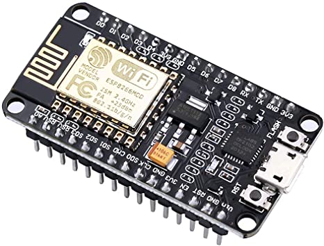
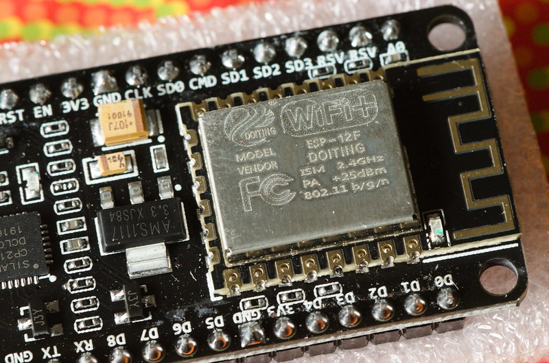
Espressif Systems Shanghai launched the game changing low cost ESP-8266 microcontroller in 2014 – a key enabler for embedded Internet of Things (IOT) development.

Internet of Things (IOT)

Adding WiFi 802.11 and Bluetooth LE wireless connectivity to system on a chip (SoC) product costing roughly price of a cup of coffee meant innovators and micro electronics DIY enthusiasts could easily interface edge smart sensor or legacy hardware systems with cloud or mobile devices.

The successor chip ESP-32 (launched 2016) introduced Xtensa LX6 processor and FreeRTOS (a real time operating system (OS) for embedded) – enabling multi-threaded applications running on multi core CPU architecture.

To add context, many even relatively complex tasks especially automation, can be run on tiny embedded 8 bit processor such as Arduino. More complex applications, video, audio signal processing, image recognition or AI require much more compute power.

ESP-32 in the eco-system sits between Arduino and more powerful systems Raspberry Pi, Windows or Embedded Linux.

Sounds great, but how does it work in practice?

ESP8266

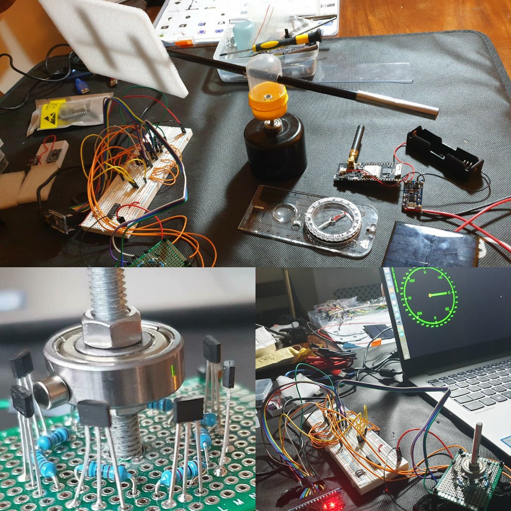
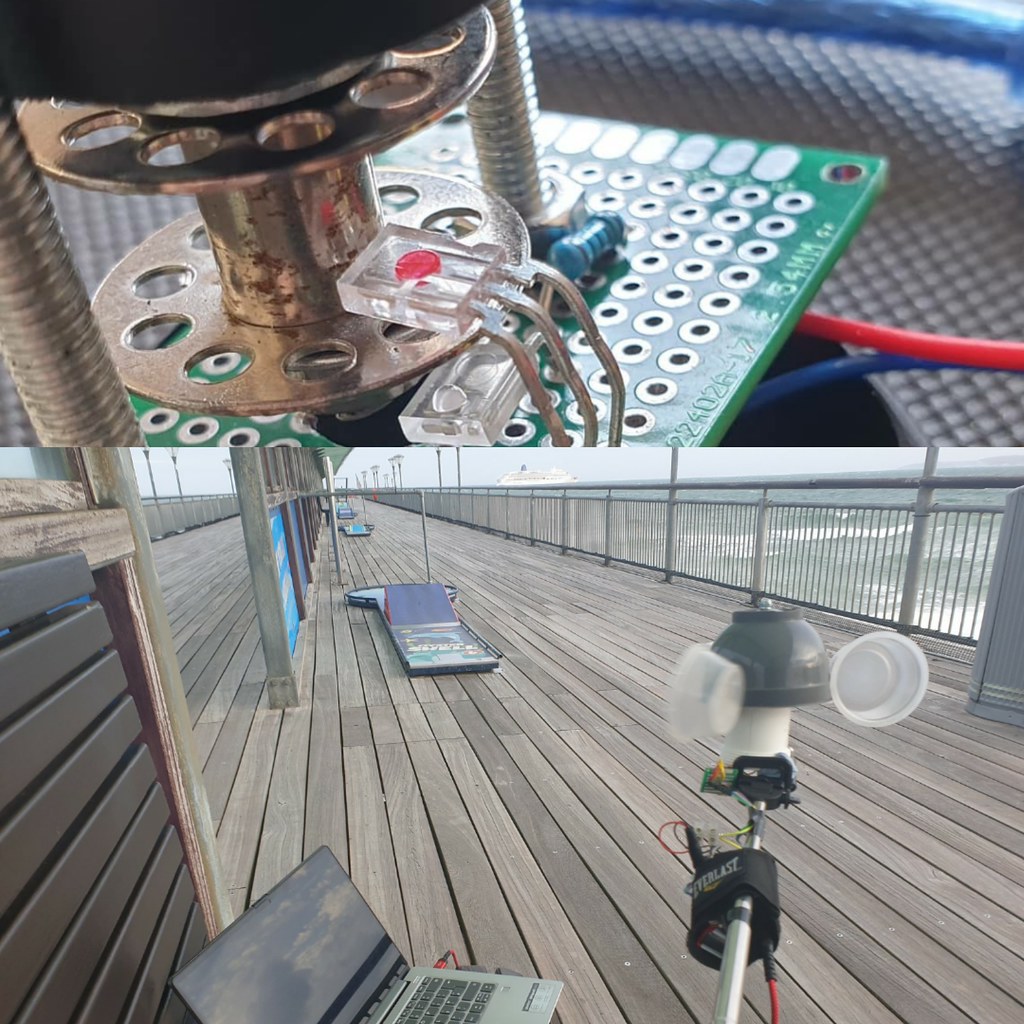
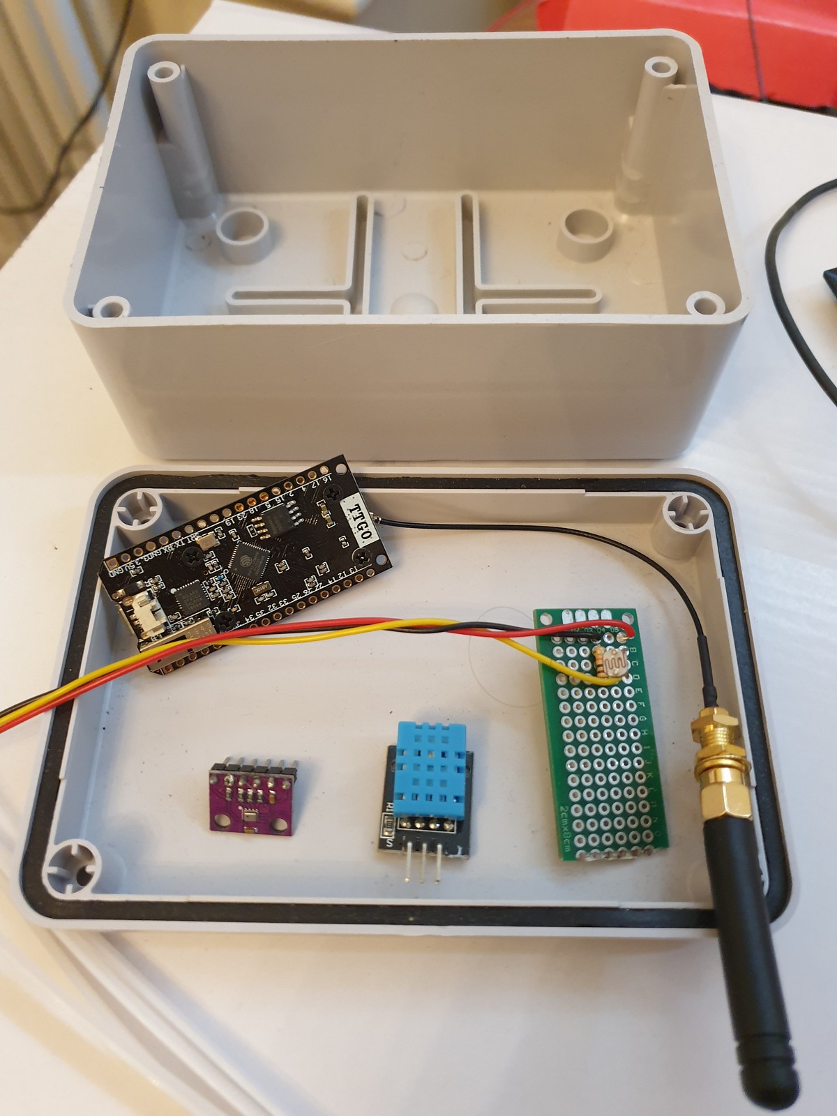
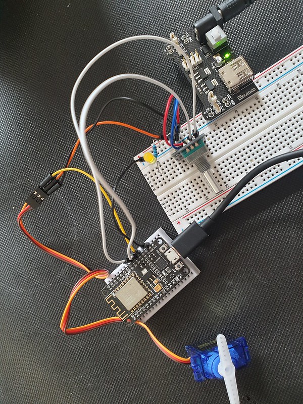
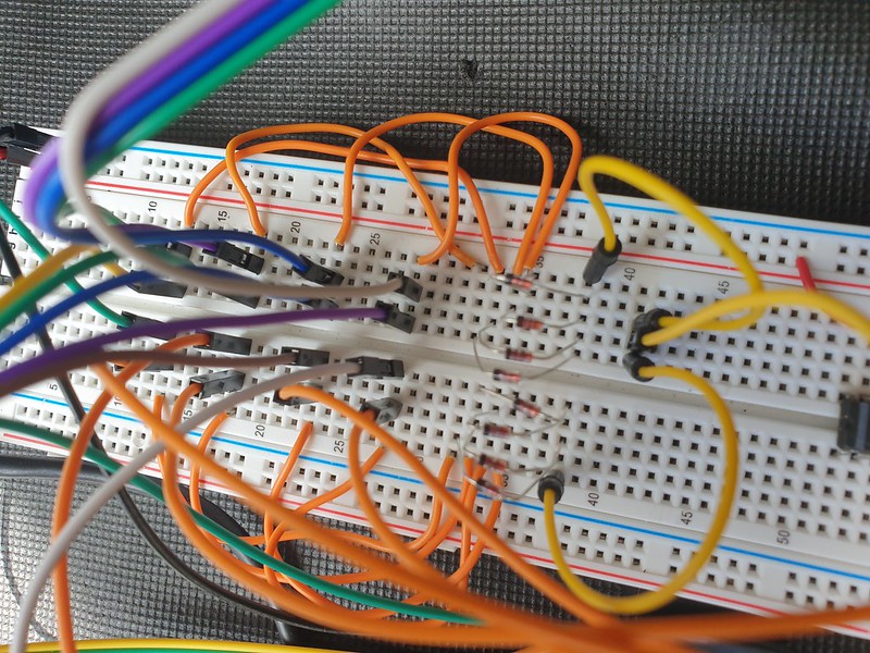
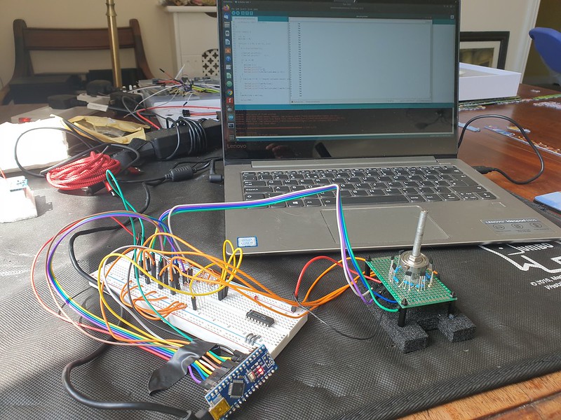
In this sketch ( https://github.com/steveio/arduino/tree/master/ESP32GPSMultiTask ) we assemble a UBLOX GPS data logger with an SD card internal storage, LoRaWAN wireless relay and an OLED display.


The goal is to demonstrate running 4 separate non-blocking tasks concurrently using FreeRTOS to schedule tasks, suspend, interrupt, queue and share data in thread-safe way with mutex semaphore locks.

Let’s take a look at the code…. concentrating on FreeRTOS multi-core multi-thread potential, rather than peripherals / sensors.

Data Structures, Multi-thread Semantics & Setup()

First, a struct to encapsulate core data model message (GPS data):

// GPS position data
struct XPosit
{
float Lat;
float Lon;
float Alt;
float Course;
float Speed;
} xPosit;

Next two semaphores to serialise reading and writing tasks to ensure data consistency:

// Semaphores to lock / serialise data structure IO
SemaphoreHandle_t sema_GPS_Gate;
SemaphoreHandle_t sema_Posit;

Then a pointer queue for passing messages between threads / tasks:

// GPS position data queue
QueueHandle_t xQ_Posit;

Here is the related setup():

sema_GPS_Gate = xSemaphoreCreateMutex();
sema_Posit = xSemaphoreCreateMutex();

xSemaphoreGive( sema_GPS_Gate );
xSemaphoreGive( sema_Posit );

Now let’s define 4 tasks:

// task handles
static TaskHandle_t xGPSTask;
static TaskHandle_t xLoRATask;
static TaskHandle_t xSDWriteTask;
static TaskHandle_t xOLEDTask;

// hexadecimal notification code
define GPS_READ_BIT 0x01
define LORA_TX_BIT 0x02
define LORA_RX_BIT 0x04
define SD_WRITE_BIT 0x06
define OLED_BIT 0x08

ISR / Interrupt for Asynchronous Non-Blocking Event Loop

The system will be driven by a periodic ISR timer raising an interrupt calling a handler routine running & managing tasks.

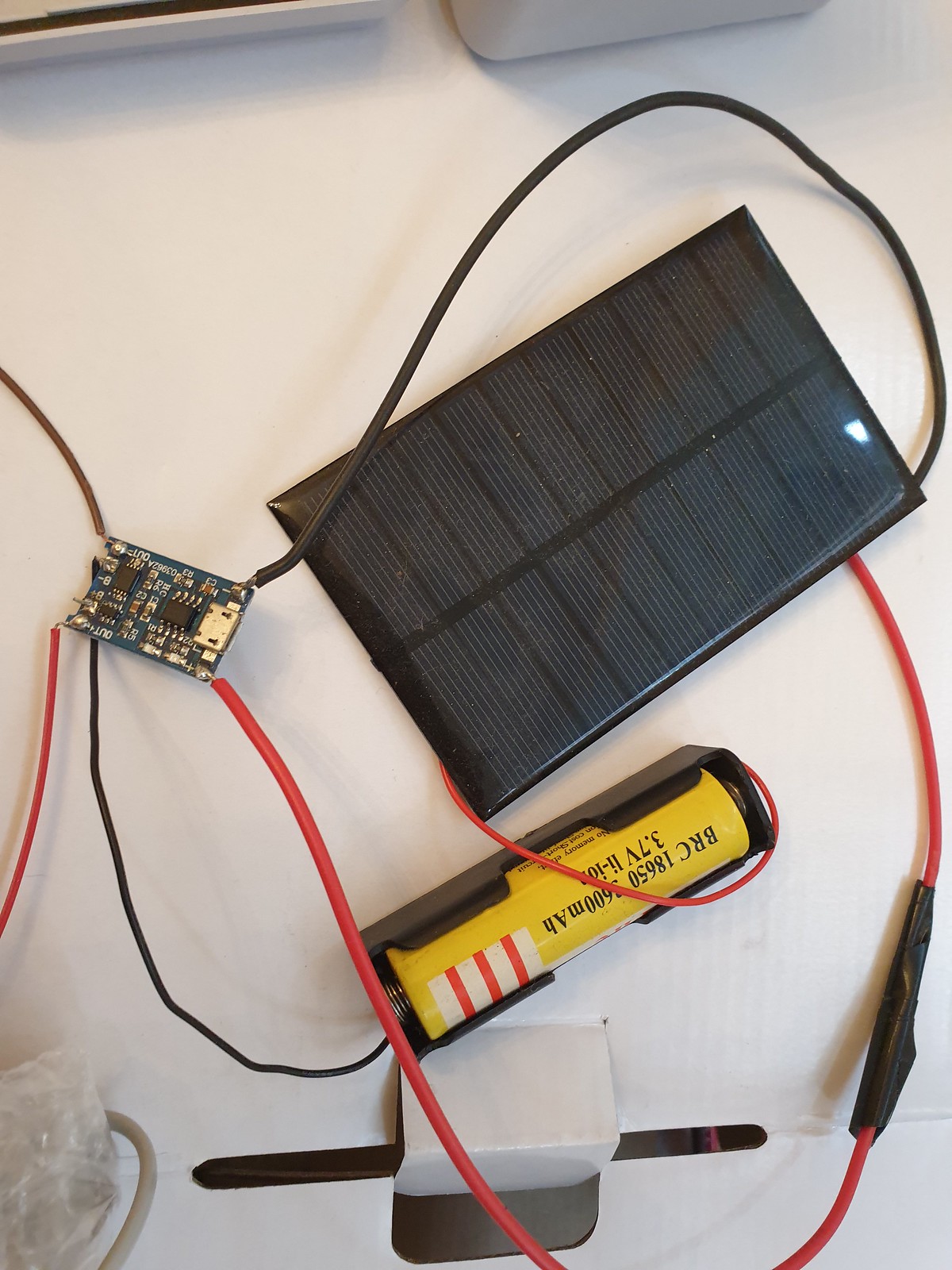
Keeping loop() empty results in non-blocking program execution, no waiting on calls to delay() in main routine – and we only need to call ISR once every ten seconds to read GPS (rather than polling loop()) – which is better for low power consumption.

Under the hood FreeRTOS works in the same way:

> FreeRTOS implements multiple threads by having the host program call a thread tick method at regular short intervals. The thread tick method switches tasks depending on priority and a round-robin scheduling scheme.
( https://en.wikipedia.org/wiki/FreeRTOS#References )

With a task based modular event driven architecture, failure of one task – if write to SD card task blocks or fails because there is no storage card present), other tasks – reading GPS messages, LoRaWAN radio transmit continue.

// ISR timer
hw_timer_t * timer = NULL;
portMUX_TYPE timerMux = portMUX_INITIALIZER_UNLOCKED;
unsigned long isrCounter = 0;

ISR Handler Function (Main control routine, replaces loop()):

// ISR Interupt Handler
void IRAM_ATTR fLoRASendISR( void )
{
portENTER_CRITICAL_ISR(&timerMux);

// Main program routine here ..

portEXIT_CRITICAL_ISR(&timerMux);
}

In setup() we schedule ISR timer:

// Configure Prescaler to 80, as our timer runs @ 80Mhz
// Giving an output of 80,000,000 / 80 = 1,000,000 ticks / second
timer = timerBegin(0, 80, true);
timerAttachInterrupt(timer, &fLoRASendISR, true);

// Fire Interrupt every 10s (10 * 1 million ticks)
timerAlarmWrite(timer, 10000000, true);
timerAlarmEnable(timer);

FreeRTOS Task (Thread) Setup

Next in setup() we describe & initialise tasks, specify which CPU core they should run on, their priority and a few other details

// create a pointer queue to pass position data
xQ_Posit = xQueueCreate( 15, sizeof( &xPosit ) );

Serial.print("Start Task fGPS_Parse() priority 0 on core 0");
xTaskCreatePinnedToCore( fGPS_Parse, "fGPS_Parse", 1000, NULL, 0, &xGPSTask, taskCore0 );
configASSERT( xGPSTask );


Serial.println("Start Task fSD_Write() priority 4 on core 1");
xTaskCreatePinnedToCore( fSD_Write, "fSD_Write", 1000, NULL, 4, &xSDWriteTask, taskCore1 ); // assigned to core 1
configASSERT( xSDWriteTask );

Serial.println("Start Task fLoRA_Send() priority 3 on core 1");
xTaskCreatePinnedToCore( fLoRA_Send, "fLoRA_Send", 1000, NULL, 3, &xLoRATask, taskCore1 ); // assigned to core 1
configASSERT( xLoRATask );

Here’s how to have a task start and wait suspended pending a notification. LoRaWAN transmit task starts and waits until read GPS notifies of new message to send; no need to constantly run radio draining battery or poll the message queue.

for( ;; )
{
/* block until task notification */
xResult = xTaskNotifyWait( LORA_TX_BIT,
                     ULONG_MAX,        /* Clear all bits on exit. */
                     &ulNotifiedValue, /* Stores the notified value. */
                     portMAX_DELAY );  /* Block indefinately */

if( xResult == pdPASS ) 
{

Executing FreeRTOS threads : ISR Main Routine

In main ISR program loop, here’s how to notify tasks:

BaseType_t xHigherPriorityTaskWoken = pdFALSE;

/* Notify (trigger) Read GPS
xTaskNotifyFromISR( xGPSTask,
                   GPS_READ_BIT,
                   eSetBits,
                   &xHigherPriorityTaskWoken );

/* Notify LoRA send task to transmit by setting the TX_BIT */
xTaskNotifyFromISR( xLoRATask,
                   LORA_WRITE_BIT,
                   eSetBits,
                   &xHigherPriorityTaskWoken );

Inter process Communication (IPC): Semaphore Mutex Locks

Concurrency & data consistency in real time and multi threaded systems requires care to ensure serial ops – a write by one thread to a data struct for example must not corrupted by another concurrent thread.

The classic answer to this is locks – mutex, semaphores. A thread requests obtains & takes a lock and other tasks block (wait, retry). The lock is revoked only when lock holding task completes or rolls back.

Here is how it’s done in FreeRTOS:

   if ( xSemaphoreTake( sema_GPS_Gate, xTicksToWait0 ) == pdTRUE )
{
 if ( xSemaphoreTake( sema_Posit, xTicksToWait1000 ) == pdTRUE )
    {
      xPosit.Lat = gps.location.lat();
      xPosit.Lon = gps.location.lng();
      xPosit.Alt = gps.altitude.meters();
      xPosit.Course = gps.course.deg();
      xPosit.Speed = gps.speed.kmph();

      xSemaphoreGive( sema_Posit );
    }


    if ( xSemaphoreTake( sema_Posit, xTicksToWait1000 ) == pdTRUE )
    {
      Serial.println("xQueueSend()");
      pxPosit = &xPosit;
      xQueueSend( xQ_Posit, ( void * ) &pxPosit, ( TickType_t ) 0 );  
      xSemaphoreGive( sema_Posit );
    }

    xSemaphoreGive( sema_GPS_Gate );
  }

FreeRTOS : Message Queue

Those interested in using Queue’s (a sized FIFO pointer linked buffer) to pass data between tasks should consult the API reference:

https://www.freertos.org/a00018.html

// Examples:

// Writing
if ( xSemaphoreTake( sema_Posit, xTicksToWait1000 ) == pdTRUE )
        {
          pxPosit = &xPosit;
          xQueueSend( xQ_Posit, ( void * ) &pxPosit, ( TickType_t ) 0 );  
          xSemaphoreGive( sema_Posit );
        }

// Reading..
struct XPosit xPosit, *pxPosit;
  
 if( xQueueReceive( xQ_Posit,
                         &( pxPosit ),
                         ( TickType_t ) 10 ) == pdPASS )
      {

Conclusion

Espressif changed the game in 2014 with ESP8266 – bringing WiFi & Bluetooth to Arduino’s eco-system of low cost interoperable sensors & components – the internet of things (IOT) long promised since at least 1980s as “smart home” concept finally came of age.

Modern mobile devices and laptops are now so incredibly complex as to be virtually indecipherable, especially at hardware / OS level – to most people, even those within IT industry.

Arduino made it possible for students, DIY enthusiasts, makers & researchers to work with Microcontrollers in a way that is relatively simple, comprehensible and fun. No longer do you necessarily need a PhD, work for tech giant or own a CPU manufacturer to build a micro-electronics project.

By adding WiFi, Bluetooth & LoRaWAN wireless, Espressif opened door to new information age of cloud connected smart sensor & control devices. IOT smart home devices & solutions from Amazon AWS and Google (Matter) are already available in marketplace.

But the option endures – those who wish to can make their own or projects or use a component approach to Internet connect existing machines.

It remains to be seen in decades to come whether people use this tech for good, to benefit people, to make things better; or for nefarious activities – stalking, tracking, surveillance; or worse AI enabled weapons…

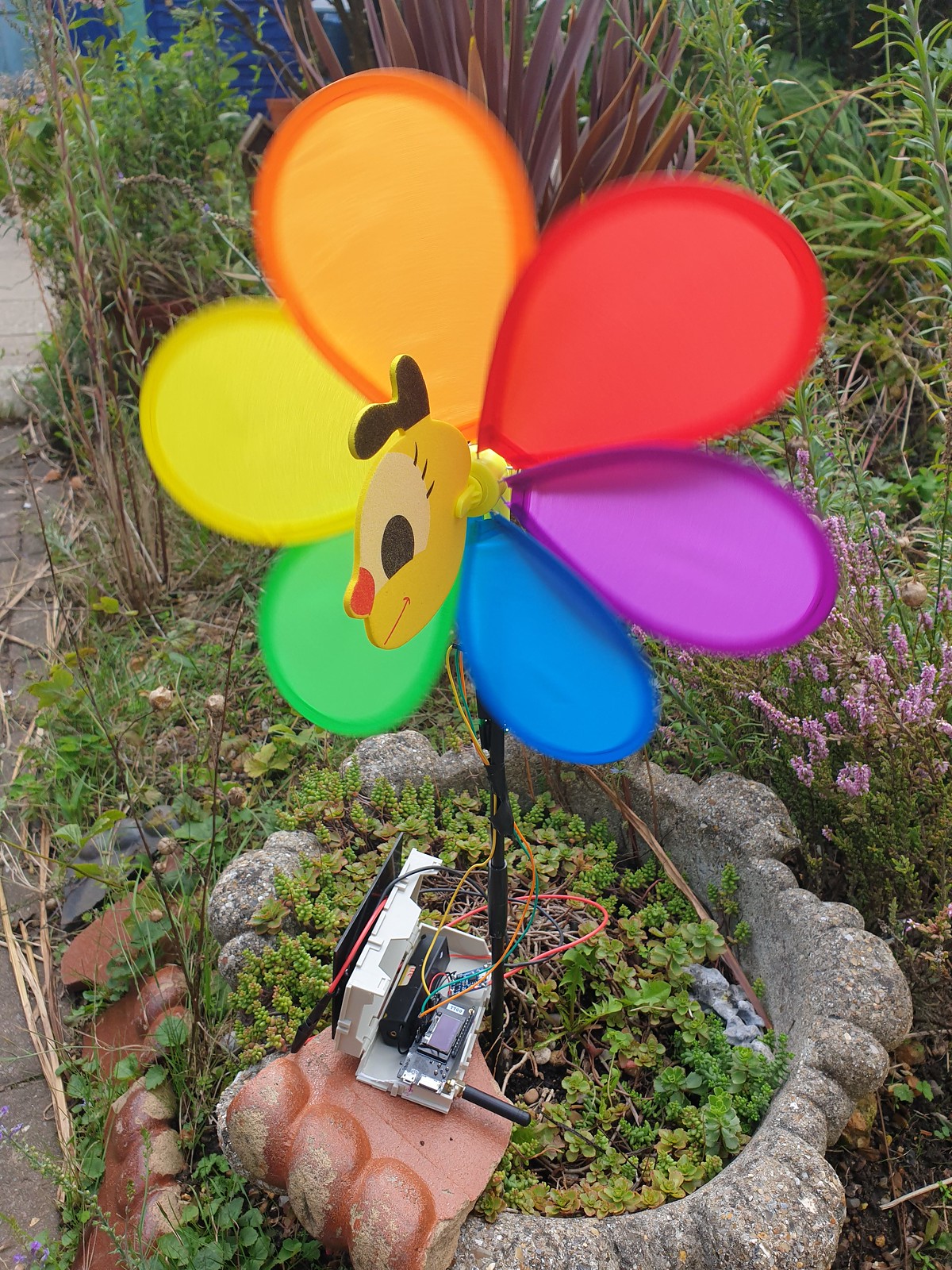
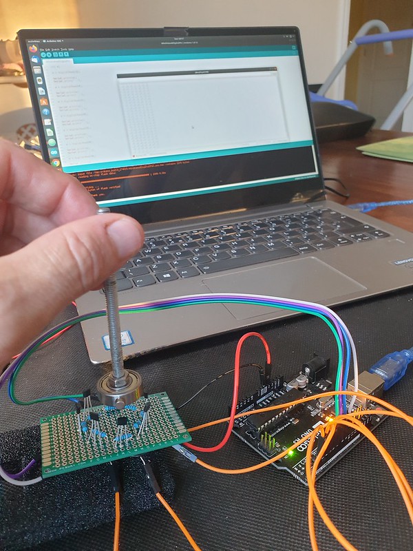
(my plan for this prototype was to add 6 axis accelerometer, attach prototype to a stunt kite, aquire some flight input data, create some cool real time web visualisations and explore some more Python SciPi, Mathplotlib & Pandas libraries (alas the prototype proved too fragile to get off the ground).

Anyway hope this tutorial helps you, it took me 30 years to even vaguely understand micro electronics hardware, multi-threading, c++…

Categories
Internet of Things sensors wearables

Wearables: Mi Band 6 Smart Fitness Tracker

Mi Band 6 is a wearable smart watch / fitness band tracker from Xiaomi with Mi Fit health mobile app.

For a time i’ve looked for an economic sport tracker band or smart watch that is waterproof, swim compatible, syncs with Strava and offers long battery life.

Crucially, what you don’t get with slim lightweight (12.8g) fitness band compared to smart watches from brands like Apple or Garmin is GPS location tracking.

To record route data you must also carry a paired GPS smart phone with Mi Fit app when cycling, running or walking.

Lack of GPS radio conversely helps preserve battery life promised as upto 14 days.

Timing, location and speed data recorded by Mi Fit appeared reasonable accurate for cycling, running & walking.

Strava is a social platform offering privacy options to obscure route start / end points, Mi Fit by default does not share route data.

GPS Elevation was not accurate beyond ~100 metre range. Multiple climbs / descents of between 20 and 150 metres were not tracked correctly (sea level promenade route displayed incorrectly as 90 metres).

Also, there is no indication from device sensors or mapping provider of incline to describe stage climb / descent.

Smart bands promise to remove need to carry a physical wallet and keys but at present Mi Band 6 only supports AliPay / WeChat which is not widely accepted in UK and there is no option to use Google or Apple Pay eWallet instead.

As a keyring it would be nice to use NFC to enter gym contactlessly. Instead of carrying seperate gym card, in theory leisure centre member app could put entry token into smart band keyring.

Who being unable to find coin or having lost key token wouldn’t rather tap smartband to open gym locker?

Mi Band 6 implements Bluetooth LE v5 but it isnt clear (without further investigation) what level of encryption and authentication are used, suggesting by default a users private biometric data could potentially be read without consent.

For secure e-payments having 2 factor authorisation, for example biometric fingerprint unlocking would prevent unauthorised use.

Onboard environmental sensing is dissapointing. Weather data appears to sync only occasionally from an online feed. It lacks an hourly local forecast and key metrics air pressure, humidity, wind speed / direction, time of sunrise / sunset and moonphase.

During sporting activities having a record of local environmental conditions from onboard temperature / humidity, barometric pressure and light level sensors combined with local forecast vastly improve data quality – full sun vs shade, hi/lo temperature, wind speed / direction affect performance.

Strava can be linked to Klimat.app to add generalised conditions to cycle rides although this is not segment specific.

Overall from amateur sports perspective rather than someone with medical background (and scientific tools to verify accuracy) Mi Band fitness health metric tracking & reporting seems impressive.

Key metrics missing from health monitoring include Blood Pressure (distinct from heartrate), breathing (respiration) rate and body temperature. Isn’t stress level dependent on these as inputs for meaningful recording?

Two minor issues, touch screen doesnt work correctly in water (swim activity should be triggered at poolside) and strap button can fly away when clipping / unclipping band, so care must be taken when removing band after swimming before entering Sauna / Steam Room (5 ATM waterproof rating excludes Spa use).

Swim tracking based on an indoor pool session is impressive, there is no need to enter pool length and distance, stroke rate and stroke classification appear accurate although Mi Fit does not display lap by lap breakdown.

For Gala’s or group training being able to contaclessly register participants bands with coach or club app would allow consolidation of timing and training data.

Also a lap timing stopwatch feature would be nice to have.

To record body weight (a key goal of most fitness programs) by default weight is manually input into Mi Fit.

Enter Xiaomi smart scales, a wireless Bluetooth enabled companion device designed (and found in practise) to sync simply and seamlessly with Mi Fit.

Mi Fit should allow users to set goals for weight loss (or gain) and show comparison to previous week / month / year.

Presently (Mi Fit v6 2.1) there doesn’t appear to be option to sync weight data to Mi Band 6.

Getting supplementary data into Mi Fit from other 3rd external sources, event timing systems, gym machines etc on completing a workout should be as easy as requesting / agreeing a Bluetooth data sync request.

Sadly no Life Fitness machines at local gym presently support Bluetooth and its not clear if Google Fit, Mi Fit or Strava have yet established an open standard interoperable and compatible with all bands, smartwatches and machine makers.

Motion sensor based activity auto detection: gesture recognition, counting and timing is not arguably without inaccuracies.

Considering underlying math complexity, long device battery life and low price point recognition of simple activities like rowing machine worked well. Yoga poses on other hand were not recognised in current version.

Behaviour Tagging feature suggests use of cutting edge AI Machine Learning – where user trains band for specific activity recognition / classification, resulting in personalised model and great accuracy for swim stroke or tennis shot recognition.

Overall Mi Band 6 has a winning low price point, impressive feature set, relatively good precision / tracking accuracy, brilliant sharp and bright OLED display and long battery life. Setup and sync with Mi Fit app and Xiaomi smart scales was simple and easy. Mi Fit dashboard app provides detailed and attractive graphical chart metrics. Finally, for fashion concious there’s a choice of inexpensive coloured and stylised replacement straps.

Xioami Mi Band 6 : from 2022 review of best waterproof swim fitness trackers:

https://www.coachmag.co.uk/fitness-trackers/6139/the-best-waterproof-fitness-trackers-for-swimmers

Categories
arduino C/C++ circuits Coding Embedded esp32 expressif Internet of Things microcontrollers MQTT sensors weather station WebSockets

SparkFun Weather Sensor Kit

Wind and Rain sensor kit newly arrived from SparkFun Electronics to upgrade an Arduino Weather Station project.

SparkFun Weather Sensor Kit, DIY prototypes, Arduino Weather Station

Also pictured are earlier DIY prototypes – a childrens bee wind spinner with hall effect sensor to count rotations, an anemometer made from recycled plastic packaging utilising a IR Led optical rotary encoder and a wind vane with eight fixed directional magnetic switches.

( more here: http://www.steveio.com/2020/07/21/weather-station-wind-vane-history-science/ and http://www.steveio.com/2020/07/21/weather-vane-hall-sensor-magnetic-rotary-encoder/ ).

Bee Windmill Anemometer with ESP32 LoRa Transmitter running on single 3.3v Li-Ion cell.
8 Durection WInd Vane with magnetic hall sensor array and WebSocket TCP web browser interface.
ESP8266 Anemometer with optical IR Led sensor, wifi connectivity and D3.js websocket provisioned UI.

( Code for these projects can be found on GitHib. )

Weather station projects are a popular accessible introduction to microelectronics; a microcontroller and sensors can be found at low cost, modular hardware design results in easy assembly and open software platforms like Arduino IDE streamline packaging and deployment of code to devices.

Analysing real time or historical time series data, from weather sensors is a lot of fun. Frameworks like R Project for Math Stats: https://www.r-project.org/ ) and Python, Pandas, Numpy & Mathplotlib provide implementations of most alogirithms and convenient data structures for importing & manipulating data.

Techniques and methods are transferable and can be applied to other domains or ontologies – finanicial, accounting data for example.

SparkFun offer an OEM Wind & Rain sensor kit manufactured by Shenzen Fine Offset Electronics, China.

With advent of 3d modelling & printing it is also feasible for an enthusiast to design and fabricate via a 3d printer custom sensor components, perhaps using template models downloaded from repos like ThingiVerse.

In competition marine OpenWind are defining what smart network connected sensors can achieve utilising Bluetooth LE to make near real time wind data available on smartphone.

Assembled SparkFun Weather Sensor Kit

Ideal for enthusiast or educator SparkFun Weather kit comes wihout circuitry,  microcontroller or software.  An add-on PCB designed for use with  Arduino / ESP32 can be purchased or Datasheet Technical Specs provide reference sensor circuit designs, not significantly complex due to use of magnetic reed switch and variable resistance technology.

MCU Sensor Control & Relay Unit – IP67 Weather Proof Enclosure, ESP32 TTGO LoRa microcontroller, light, temperature and air pressure sensors.

Traditionally 433MHz RF has been used for base station to transmitter devices. A popular project is to use Arduino, a cheap 433Mhz receiver and a library to read data from a commercial weather station designed for use with manufacturers display, enabling this data to be provisioned to the cloud.

For data transmission non GPRS (cellular) options include Bluetooth LE (range ~100 metres) or LoRa (Long Range Low Power Network – range between 300 – 10km depending on antenae) offering cableless wireless connectivity allowing remote sensor situation with no associated network costs.

At data layer WebSockets and MQTT for IOT devices are challenging serial protocols as defacto lightweight, reliable & easy to implement transport relays.

Apart from range and connectivity goals of low power consumption for efficient and long battery running time combined with solar charging enable devices to run standalone for long periods.

Is a single 3.3v Li-Ion Battery Cell Sufficient? TP405 Charging Module & Solar Panel

Weather Stations have applications beyond meteorology in smart agriculture, industrial, safety monitoring and for wind or wave based leisure pursuits. 

Assembling DIY Arduino Mega Weather Station v1.0

More generally Internet of things wireless networked smart sensor platforms can be used for many purposes and combined with AI and Machine Learning algorithms useful insight and patterns within data can be analysed, classified and predicted. 

SparkFun Smart ETextiles & Conductive Thread Kit

Personally, I really enjoyed SparkFun Arduino LilyPad e-textile, smart fabrics and conductive thread kit, so looking forward to now spinning up the Weather Station sensors!

Categories
arduino C/C++ Coding Embedded esp32 esp8266 Internet of Things microcontrollers Software

Timed Device – Simple & lightweight scheduling for on/off devices

Timed Device is a library for Arduino / ESP 8266/32 embedded platforms written to emulate a simple plug in timer for an electrical device, where pins in a ring are set to define hour/minute status. Designed to be simple and lightweight optimisation is for low memory.

Arduino ATMega328 and related embedded microcontrollers provide internal high precision clock based timers suitable for events with second, millisecond and fine granularity (to clock speed 8 / 16 mhz).

When lower precision is sufficient, recurring timers for example where an event should occur on a specific minute, hour or day of week, a lightweight implementation can be achieved and storage for internal data structures can be optimised, a significant win factor on embedded systems where memory use is constrained.

The library follows an object orientated design pattern resulting in an extensible, scale-able architecture suitable for controlling from one to a large number of devices sharing a common timing core with each timed device class able to implement specific instructions for switching on/off.

Example use cases:

  • Switch lights or any electrical relay device on/off
  • Activate a pump or valve
  • Open/Close blinds, curtains or shutters
  • Control a fan, heat source or air conditioning

How to Define Time

In C time.h the tm structure has the following definition −

struct tm {
   int tm_sec;         /* seconds,  range 0 to 59          */
   int tm_min;         /* minutes, range 0 to 59           */
   int tm_hour;        /* hours, range 0 to 23             */
   int tm_mday;        /* day of the month, range 1 to 31  */
   int tm_mon;         /* month, range 0 to 11             */
   int tm_year;        /* The number of years since 1900   */
   int tm_wday;        /* day of the week, range 0 to 6    */
   int tm_yday;        /* day in the year, range 0 to 365  */
   int tm_isdst;       /* daylight saving time             */
};

While this structure is useful for point in time defined events, in case of a recurring timers this can be simplified.

If hour precision is sufficient, a single 32 bit mask can be used:

// Bitmask defines hours (from 24h hours) device is on (1) or off (0)
// 0b 00000000 23 22 21 20 19 18 17 16 15 14 13 12 11 10 9 8 7 6 5 4 3 2 1 0
long hourTimerBitmask =0b00000000001111111111111111100000;

Day of week (bit index 0 = Sunday – 6 Saturday) can be defined similarly:

long dayOfWeekTimerBitmask = 0b0101010;

With bitmasks we can determine if an event is scheduled using bit shifts:

// Check if bit at pos n is set in 32bit long l
bool Timer::_checkBitSet(int n, long * l)
{
  bool b = (*l >> (long) n) & 1U;
  return b;
}

To check if an hour timer bitmask is on/off for 7am:

bool isSet = _checkBitSet(7, hourTimerBitmask)

For a more detailed guide to Bitmasks, shifts and bitwise operations see this article.

An on / off time occuring at specific (hour:minute) intervals can be defined as:

typedef struct tmElements_t {
  uint8_t Min;
  uint8_t Hour;
};

We can use a struct as container for an array of 1..n pairs of on/off times occurring on specified weekdays:

#define SZ_TIME_ELEMENT 2

typedef struct tmElementArray_t {
  unsigned long Wday;   // bitmap - days of week (bit index 0 = Sun - 6 Sat)
  struct tmElements_t onTime[SZ_TIME_ELEMENT];
  struct tmElements_t offTime[SZ_TIME_ELEMENT];
};

With these data structures we can setup up a pair of on/off times (08:00 -> 08:10 and 19:00 -> 19:30) to occur on Sun, Mon, Thur, Fri:

// create variables to define on/off time pairs
struct tmElements_t t1_on, t1_off, t2_on, t2_off, t3_on, t3_off;
struct tmElementArray_t timeArray;

t1_on.Hour = 8;
t1_on.Min = 0;
t1_off.Hour = 8;
t1_off.Min = 10;

t2_on.Hour = 19;
t2_on.Min = 0;
t2_off.Hour = 19;
t2_off.Min = 30;

timeArray.n = 2; // number of time pairs
timeArray.Wday = 0b00110011; // define days of week timer is active on

timeArray.onTime[0] = t1_on;
timeArray.offTime[0] = t1_off;

Check if a recurring timer is set

How we check a timer (whether bitmask or time based) depends on the type of time source we have.

Most familiar time source on Arduino is millis() function providing elapsed time in milliseconds since device reset / startup.

This is useful for timing events in a non-blocking way at recurring intervals:

if (millis() >= sampleTimer + sampleInterval)
{
  ... do something
  sampleTimer = millis();
}

But what if we want to schedule in terms of hour, minute or day of week based on current time?

To achieve this a micrcontroller is combined with a Real Time Clock module, providing a battery backed time source that once synced (for example to an NTP time source) maintains current time even when device is switched off.

Arduino Nano in pin breakout board with DS3231 Real Time Clock Module

Arduino DS1307/3231 RTC modules have supporting libraries (for example RTCLib from Adafruit) to obtain current time usually in form of:

DateTime now = rtc.now();

Where DateTime object provides an API to return specific time elements:

Serial.print(now.hour());
Serial.print(':');
Serial.println(now.minute());
Serial.print(now.dayOfTheWeek());

Is an event scheduled (at a specific point in time)?

In C function overloading can be used to provide multiple interfaces to an isScheduled() method according to timer precision / time source type :

bool isScheduled(int h);
bool isScheduled(int h, int d);
bool isScheduled(int m, int h, int d);
bool isScheduled(unsigned long ts);

(Where h = hour, m = minute, d = week day)

Most users of Unix based systems are familiar with “timestamp” a 32bit unsigned long representing elapsed seconds since a fixed point in time, the Unix Epoch which occurred 1970-01-01 00:00:00 UTC.

Unix is not unique in using a reference Epoch, they have been used in calender systems worldwide since ancient times.

We can obtain current timestamp on Linux via command line with date command:

stevee@ideapad-530S:~$ date +%s
1620155520

A timestamp as a time source can be used with any timer definition, whether point in time or recurring. It has advantage (compared to using numeric representations of individual time elements) that a single long number can be used for computation and conversion and we don’t need to worry about problems like variable number of days in month or leap years.

Timestamps and time and date conversion tricks

For a timer defining specific days of week, the first question might be how to obtain weekday from a unix timestamp (elapsed seconds since epoch)?

int weekday = (floor((ts / 86400)) + 4) % 7;

1970-01-01 was a Thursday, dividing timestamp by 86400 (number of seconds in a day: 24 * 60 * 60) gives number of days since epoch, adding 4 shifts start day to Sun and modulo 7 returns day of week.

To check if a timestamp is within range of one or more on/off time pairs (specified in hh:mm format as uint8_t Min; uint8_t Hour;) first we convert all time elements to elapsed seconds:

// convert fully qualified timestamp to elapsed secs from previous midnight
unsigned long elapsedTime = ts % SECS_PER_DAY;

unsigned long s1, s2, onTime, offTime;

// check each timeArray on/off pair
for (int i = 0; i < _timeArray->n; i++)
{
  s1 = _timeArray->onTime[i].Min * SECS_PER_MIN;
  s2 = _timeArray->onTime[i].Hour * SECS_PER_HOUR;
  onTime = s1 + s2;
  s1 = _timeArray->offTime[i].Min * SECS_PER_MIN;
  s2 = _timeArray->offTime[i].Hour * SECS_PER_HOUR;
  offTime = s1 + s2;

  if (elapsedTime >= onTime &amp;&amp; elapsedTime <= offTime)
  {
    return true;
  }
}

Conclusion

While TimedDevice library is non-blocking (it does not technique like delay()) it is not truely asynchronous or event driven as each device implementing a timer must poll for an event on each iteration of loop().

This could constrained to checking once per second/minute/hour but perhaps a better architecture would be to use either RTC DS3231 squarewave or Arduino internal timer to register and trigger an interrupt with an associated handler only when an event is due to occur.

Similarly if either a very large number of events are scheduled, or a large set of timed devices created, it would be sensible to register these with a scheduler (akin to a CPU scheduler) tasked with sorting, prioritising and actioning event queue in an efficient way, which might utilise a multi-threaded approach on multi-core CPU architectures.

Source code for Timed Device library can be found on GitHub including a full Arduino sketch example for defining a solenoid valve timer with an RTC timesource.

Categories
arduino Coding Embedded Internet of Things Python weather station

Sunrise / Sunset Time visualised with Python, Pandas & Matplotlib

We can use Python Pandas & Mathplotlib libraries to quickly visualise sunrise / sunset timing data, but how to plot time as a number on a graph?

Sunrise / Sunset times are computed on my Arduino Weather Station using SunMoon library ( https://github.com/sfrwmaker/sunMoon ). Incredible that such a tiny 8 bit machine architecture can run this relatively complex algorithm with ease.

Data is logged every 30 mins to daily files stored on SD card in JSON text format.

stevee@ideapad-530S:~/Arduino/projects$ ls  ./data/weather/*.TXT | head -3
./data/weather/20200816.TXT
./data/weather/20200817.TXT
./data/weather/20200818.TXT

Once files are transferred to a Linux computer, a bash script pre-processor (a useful technique on large datasets where syntax modifications are necessary) is used to reformat data as valid array of JSON objects –

stevee@ideapad-530S:~/Arduino/projects$ cat weather_preprocess.bash
#!/bin/bash

for f in data/weather/*.TXT; do
    j="${f%.*}"
    grep "^\[" $f | sed 's/\[//g' | sed 's/\]/,/g' | sed '$ s/.$//' | sed '$ s/.$//'  > $j.json
    sed -i '1 i\\[' $j.json
    echo "]" >> $j.json
    echo $j.json
done

JSON data is an array of objects where each row represents a single log entry indexed by unix timestamp.

Columns represent sensor & computed data – temperature, humidity, air pressure, sun elevation, surise / sunset time and moon phase.

stevee@ideapad-530S:~/Arduino/projects/python$ head -20 ../data/weather/20201015.json
[
{"ts":1602720026,"t":15.5,"h":88,"l":986,"p":102141,"t2":18.8,"a":0.414837,"w":697,"el":-47.86353,"az":2.618189,"lat":50.7192,"lon":-1.8808,"sr":"07:31","ss":"18:14","mn":28},
{"ts":1602720059,"t":15.5,"h":88,"l":988,"p":102140,"t2":18.8,"a":0.166463,"w":692,"el":-47.85925,"az":2.82748,"lat":50.7192,"lon":-1.8808,"sr":"07:31","ss":"18:14","mn":28},
...

Assuming a working Python (v2x) installation and dependencies (Pandas, Mathplorlib, Datetime) are present, we include required libraries and import data from file using Pandas creating a DataFrame in memory table structure –

import os
import json

import matplotlib as mpl
import matplotlib.dates as mdates
import matplotlib.pyplot as plt
import matplotlib.dates as mdates
import pandas as pd
from datetime import datetime as dt

days_to_extract = 90;
path = "../data/weather/"
files = []
frames = []

### Data file path and file format 
for (path, dirs, f) in os.walk(path):
    files = [ fi for fi in f if fi.endswith(".json") ]

### Load JSON data
def load_json_data(filepath, frames):
    with open(filepath) as f:
        d = json.load(f)
        df = pd.DataFrame(d)
        frames.append(df)

### process n days datafiles
for f in files:
    filename = path+f
    bits = os.path.splitext(f)
    datestr = bits[0]
    dtm = datetime.strptime(datestr, '%Y%m%d')
    if dtm >= datetime.now()-timedelta(days=days_to_extract):
    load_json_data(filename,frames)

# complete dataset as DataFrame
df = pd.concat(frames)

In dataset although frequency for sunrise / set times is daily, these are actually logged every 30 mins, creating many duplicate entries –

print df['sr'];

datetime
2021-01-19 00:00:26 17:37
2021-01-19 00:00:59 17:37
2021-01-19 00:01:26 17:37
2021-01-19 00:01:59 17:37
2021-01-19 00:02:26 17:37

To get one entry per day sunrise/set timing column data is resampled to daily frequency ( .resample(‘1D’) ) and any null rows are dropped with .dropna().

This is equivilent to a relational database roll-up or group by query.

sr = df['sr'].resample('1D').min().dropna()
ss = df['ss'].resample('1D').min().dropna()

Now we have a single daily time entry row indexed by date.

2021-01-18 17:35
2021-01-19 17:37
2021-01-20 17:38
2021-01-21 17:40
2021-01-22 17:41
Name: ss, Length: 93, dtype: object

To plot times on Y-Axis values from Pandas Series are extracted into a simple 2d array list.

We call datestr2num() from mathplotlib.dates ( converts date/time string to the proleptic Gregorian ordinal ) to format time as a number –

srt = np.array(sr.values.tolist())
srt = mpl.dates.datestr2num(srt)
sst = np.array(ss.values.tolist())
sst = mpl.dates.datestr2num(sst)

giving values that can be plotted –

[737824.30416667 737824.30486111 737824.30625 737824.30763889
737824.30833333 737824.30972222 737824.31111111 737824.31180556
…]

A linear scatter plot can then be rendered with a few formatting options specified

fig = plt.figure()
ax = fig.add_subplot(111)
ax.set_title('Sunrise (GMT) Oct 2020-Feb 2021 for Bournemouth 50.7192 N, 1.8808 W')
ax.plot_date(sr.index, srt, '-ok', color='red', markersize=4)
ax.yaxis_date()
ax.yaxis.set_major_formatter(mdates.DateFormatter('%I:%M %p'))
fig.autofmt_xdate()

The result is a curve which shows day light hours being influenced as Mid Winter solstice (shortest day) Dec 21st is passed.

Sunrise times visualised as scatter plot
Sunset times

For more info and examples of real time series data charting in Python: https://www.dataquest.io/blog/tutorial-time-series-analysis-with-pandas/

Discussion of Arduino Sunrise / Sunset libraries: http://www.steveio.com/2020/09/03/sunrise-sunset-is-arduino-ahead-of-its-time/

Categories
arduino C/C++ esp8266 Internet of Things Python Software WebSockets

WebSocket Binary – ESP8266 to Web Browser

Binary wire protocols are long established for embedded machine to machine (M2M) communication, network applications and wireless radio data transmission.

Internet of Things (IOT) devices, real time sensors, robotics, smart home of industrial machine control data also demand efficient, low latency & lightweight data communications.

WebSockets ( RFC6455 ) protocol brings native support for binary framed messaging to web browser clients, offering a compact lightweight format for fast and efficient endpoint messaging.

Why use binary format data messaging?

Compared to serialisation of more complex text based wire formats, binary is lightweight and requires minimal storage / bandwidth and processing.

Taking an example key/value command data message:

// JSON encoding
{"cmd":101,"value":180}
23 * 2 = 46 bytes

// CSV plain text encoding
101,180\n
9 * 2 = 18 bytes 

// Binary
101 180
int (4 bytes) + int(4 bytes)
4+4 = 8 bytes

In case of high performance applications supporting a large number of clients or very high frequency of data exchange, minimising data size, bandwidth and processing becomes an important priority.

Binary wire protocols are long established for embedded M2M messaging

Taking as a simple example an embedded ESP8266 WiFi device, message gateway and web browser client, data serialisation and bidirectional binary framed WebSocket data exchange are demonstrated.

ESP8266 Byte Array Serialisation

Internally data is represented in embedded microcontrollers as ones and zeros, sequences of bits arranged in addressable memory.

Higher level programming language abstraction provides human readable textual labels and in case of C/C++ associated type information.

Lets define a mixed type data structure that could be some kind of sensor or message data payload –

    // define mixed type data struct
    struct Data
    {
        int id;
        float v1;
        float v2;
        unsigned long v3;
        char v4[20];
    };

    struct Data data;

    // populate data values
    data.id = 67;
    data.v1 = 3.14157;
    data.v2 = -7.123;

    unsigned long ts = millis();
    data.v3 = ts;

    char c[20] = "N NE E SE S SW W NW";
    strncpy(data.v4, c, 20);

To access underlying bytes, a pointer to data structure address is created –

    uint8_t * bytePtr = (uint8_t*) &data;    
    webSocket.sendBIN(bytePtr, sizeof(data));

Data pointer and length are passed to WebSocket send method “webSocket.sendBIN()”, byte range is read, packaged (framed) according to protocol specification and written to TCP/IP network socket.

Hexidecimal and Binary text representation of in memory data structure can also be displayed –

void printBytes(const void *object, size_t size)
{
    const uint8_t * byte;
    for ( byte = (uint8_t *) object; size--; ++byte )
    {
        Serial.print(*byte, HEX);
        Serial.print("\t");
        Serial.println(*byte, BIN);
    }
    Serial.println('\n');
}

Python WebSocket Server

A Python3 middleware hosts WebSocket server and acts as a message relay gateway.

Binary WebSocket messages can be decoded in Python, the struct module performs conversions between Python data types and C structs –

async def wsApi(websocket, path):
    try:
        async for message in websocket:
            print('User-Agent: '+ websocket.request_headers['User-Agent'])
            print('Sec-WebSocket-Key: '+websocket.request_headers['Sec-WebSocket-Key'])
            print('MessageType: '+str(type(message)))
            print(message);
            print('Hex: '+message.hex());

            if isinstance(message, (bytes, bytearray)):

                i = message[:4];
                print(i);
                tuple_of_data = struct.unpack("i", i)
                print(tuple_of_data)

                tuple_of_data = struct.unpack_from("f", message, 4)
                print(tuple_of_data)

                tuple_of_data = struct.unpack_from("f", message, 8)
                print(tuple_of_data)

                tuple_of_data = struct.unpack_from("i", message, 12)
                print(tuple_of_data)

                tuple_of_data = struct.unpack_from("20s", message, 16)
                print(tuple_of_data[0])

                ## forward message
                await asyncio.wait([user.send(message) for user in USERS])

To index into byte array and read a number of bytes according to data type being unpacked Python’s array slice method “i = message[:4]” can be used where [<from>:<to>] specifies start/end positions.

Method struct.unpack_from() is another approach, taking as parameters a format character specifying data type (“i” – integer, “f” – float), data buffer and an index (in bytes) to read from.

Here is decoded binary message output including some WebSocket headers –

User-Agent: arduino-WebSocket-Client
Sec-WebSocket-Key: zoJ0aR/5XunSvEKKcUkWfQ==
MessageType: <class 'bytes'>
b'C\x00\x00\x00|\x0fI@\x9e\xef\xe3\xc0\xb9\x17\x00\x00N NE E SE S SW W NW\x00'
Hex: 430000007c0f49409eefe3c0b91700004e204e45204520534520532053572057204e5700
b'C\x00\x00\x00'
(67,)
(3.1415700912475586,)
(-7.123000144958496,)
(6073,)
b'N NE E SE S SW W NW\x00'

Web Browser – Binary Encode/Decode in JavaScript

In web browser, JavaScript primitives Blob, ArrayBuffer and TypedArray perform a similar conversion.

Firstly, received WebSocket messages (event object) can be debugged to console –

 websocket.onmessage = function (event) {
    console.log(event);

Binary framed data payload is reported as type “Blob” (raw data) of length 36 bytes –

Chrome Developer Tools console log for WebSocket Binary message receieve event

To de-serialise message, raw data Blob is converted asynchronously using FileReader API to ArrayBuffer, a generic fixed length binary data buffer –

    if (event.data instanceof Blob)  // Binary Frame
    {
      // convert Blob to ArrayBuffer
      var arrayPromise = new Promise(function(resolve) {
          var reader = new FileReader();

          reader.onloadend = function() {
              resolve(reader.result);
          };

          reader.readAsArrayBuffer(event.data);
      });

When promise is fulfilled, ArrayBuffer can be read using typed views (Uint32Array, Uint32Array) for integer (including long) and float types, TextDecoder API is used to decode character array –

arrayPromise.then(function(buffer) {

          // Decoding Binary Packed Data

          // int (4 bytes)
          var arrInt = new Uint32Array(buffer);
          var id = arrInt[0];
          console.log("id:"+id);

          // 2x float (4 bytes)
          var arrFloat = new Uint32Array(buffer,4);
          var v1 = arrFloat[0];
          var v2 = arrFloat[1];
          console.log("v1: "+v1);
          console.log("v2: "+v2);

          // long (4 bytes)
          var v3 = arrInt[3];
          console.log("v3:"+v3);

          // character data (20 bytes)
          var uint8Array = new Uint8Array(buffer,16);
          var string = new TextDecoder("utf-8").decode(uint8Array);
          console.log(string);
      });

JavaScript Binary Data Encoding

Binary data can also be encoded from native JavaScript. TypedArrays created for each data type – integer, float, long and character array are populated and packed into an ArrayBuffer suitable for use as WebSocket data payload –

console.log("Binary Encode example");

// Binary Encode example
var buffer = new ArrayBuffer(36)
var arrInt =   new Uint32Array(buffer, 0, 1);
arrInt[0] = 67;
var arrFloat = new Float32Array(buffer, 4, 2);
arrFloat[0] = 3.14157;
arrFloat[1] = -7.123;

var arrInt2 =   new Uint32Array(buffer, 12, 1);
arrInt2[0] = Date.now();

var uint8Array = new Uint8Array(buffer,16);
var charBuffer = new TextEncoder("utf-8").encode("N NE E SE S SW W NW");

for(var i = 0; i<charBuffer.length; i++)
{
  uint8Array[i] = charBuffer[i];
}

// send binary data
websocket.send(buffer);

At message gateway, logs demonstrate parity between data packed by embedded device and those sent from web browser client –

User-Agent: Mozilla/5.0 (X11; Linux x86_64) AppleWebKit/537.36 (KHTML, like Gecko) Chrome/69.0.3497.100 Safari/537.36
Sec-WebSocket-Key: 1TD9Zp71cMTivUbj+QSx5w==
MessageType: <class 'bytes'>
b'C\x00\x00\x00|\x0fI@\x9e\xef\xe3\xc0\x07\x1c\xff\x91N NE E SE S SW W NW\x00'
Hex: 430000007c0f49409eefe3c0071cff914e204e45204520534520532053572057204e5700
b'C\x00\x00\x00'
(67,)
(3.1415700912475586,)
(-7.123000144958496,)
(-1845552121,)
b'N NE E SE S SW W NW\x00'

Limitations / Drawbacks

Compared to UTF-8 text formats (XML, JSON) packed binary data has significant disadvantages –

  • legibility – text based key/value formats are easy to read, manipulate and maintain
  • fixed frame boundaries – using positional byte sequence indexes means even small changes to message structure, size or field position require updates to consumer client code
  • endianess / alignment / padding must be maintained consistently, compiler and platform implementation differences may occur

Security

WebSockets Secure (WSS) offers transport layer security (TLS) to encrypt data streams. An authentication and authorisation strategy (challenge/response password, token or certificate based) for client identification should also be deployed. Cryptographic message digest signing or encryption might also be used as extra protection for critical data.

Categories
C/C++ esp8266 Internet of Things microcontrollers WebSockets

ESP8266 IOT Microservo WebSocket

Internet of things devices can be networked wirelessly over internet and integrate easily with cloud, mobile and web applications.

WebSockets ( RFC6455 ) run on a variety of platforms including embedded systems and web browsers enabling low latency bidirectional binary socket communication over TCP/IP.

ESP8266 is a low cost Wi-Fi micro-controller compatible with Arduino open-source electronics framework designed for networked sensor, robotics and micro-electronic control applications.

A microservo controlled by ESP8266 with web & mobile interface

WebSocket MicroServo

In a simple example a micro-servo reports position data and is controlled via a potentiometer (rotary encoder), web and mobile interfaces.

This tutorial demonstrates:

  • Microservo / Potentiometer GPIO control
  • ESP8266 WebSocket Client
  • Binary format Messaging
  • Python WebSocket Library to synchronise state between clients
  • Responsive HTML5 / Javascript Browser Control Interface

Circuit Wiring

  • 5v regulated DC power supply
  • Microservo connected to ESP8266 GPIO 15
  • 100k Potentiometer – CLK -> GPIO 12, DT -> GPIO 13

Microservo Setup

Microservo power is provided by an external regulated 5v DC power supply sharing a common ground connection to microcontroller.

Servo library initialisation and global variables –

#include <Servo.h>
int servoPin = 15;
int angle; // current angle (degrees)
int servoStartAngle = 90; // initial position
int limit = 90; // range of servo in degrees
Servo Servo1;

// in setup()
Servo1.attach(servoPin);
rotateServo(0);

Servo position is set in a function by passing angle in degrees as a parameter –

void rotateServo(int angle)
{
  Serial.print("RotateServo: ");
  Serial.println(angle);
  Servo1.write(angle);
}

Potentiometer / Rotary Encoder Setup

Potentiometer, a type of incremental rotary encoder based on variable resistance, allows relative rotary motion to be tracked, 2 out-of-phase output channels indicate direction of travel.

#define outputA 12 // Rotary Encoder #1 CLK
#define outputB 13 // Rotary Encoder #2 DT

int counter = 0; // rotary encoder incremental position
int aState; // rotary encoder state comparator
int aLastState;  

void setup() {
   pinMode(outputA,INPUT);
   pinMode(outputB,INPUT);
       
   aLastState = digitalRead(outputA);
}

Rotary encoder CLK and DT pins are compared to determine direction of rotation. Calling map() converts counter (relative position) to angle –

void readRotaryEncoder()
{  

  aState = digitalRead(outputA);

   if (aState != aLastState){     
     // If the outputB state is different to the outputA state, that means the encoder is rotating clockwise
    if (digitalRead(outputB) != aState) { 
      if (counter < limit)
      {
        counter ++;
        angle = map(counter, -90, 90, 0, 180);
        rotateServo(angle);
      }
    } else {
      if (counter + limit > 0)
      {
        counter --;
        angle = map(counter, -90, 90, 0, 180);
        rotateServo(angle);
      }
    }
  } 
  aLastState = aState;
}

ESP8266 microcontroller, Potentiometer (Rotary Encoder), Microservo, 5v DC power supply

Websocket Binary Message Framing

WebSocket protocol natively supports binary framed messaging, offering a compact lightweight format for fast and efficient endpoint messaging.

To report and update microservo position command messages are passed between control interfaces and microcontroller as binary data.

A Python service running on server creates WebSocket and maintains and synchronises shared application state between connected clients.

In web browser user interface, Javascript also has native support for (un)packing binary data.

Data Serialisation

A C struct data_t encapsulates two fields – “cmd” (unit8_t) and “value” (int) – two commands are defined, one to report servo position and another to set a new position, value represents an angle.

To assist serialisation data_t is wrapped in a packet union –

// data message
typedef struct data_t
{
  uint8_t cmd;
  int value;
};

// message packaging / envelope
typedef union packet_t {
 struct data_t data;
 uint8_t packet[sizeof(struct data_t)];
};

#define PACKET_SIZE sizeof(struct data_t)

#define CMD_SERVO_ANGLE 12 // command to report servo position
#define CMD_SERVO_ROTATE 13 // move servo to a specified position

Instances of data structs are created representing send and receive messages.

// send / receive msg data structures
union packet_t sendMsg;
union packet_t receiveMsg;

// messaging function prototypes
void readByteArray(uint8_t * byteArray);
void writeByteArray();
void printByteArray();

// buffer 
uint8_t byteArray[PACKET_SIZE];

Methods allow struct data to be written and read from byte array buffer –

// read bytes from buffer
void readByteArray(uint8_t * byteArray)
{
  for (int i=0; i < PACKET_SIZE; i++)
  {
    receiveMsg.packet[i] = byteArray[i];
  }
}

// write data to buffer
void writeByteArray()
{
  for(int i=0; i<PACKET_SIZE; i++)
  {
    // msg into byte array
    byteArray[i] = sendMsg.packet[i]; 
  }
}

ESP8266 Wifi / Websocket Setup

Details for setting up ESP8266 wifi can be found here.

ESP8266 Websocket library is added by including headers, defining server IP address / port / path and creating a WebSocketsClient class instance.

#include <WebSocketsClient.h>

WebSocketsClient webSocket;

const char* ws_server = "192.168.1.127";
const uint16_t ws_port = 6789;
const char* ws_path = "/";

In setup WebSocket library is initialised –

void setup() {
    ...

    // server address, port and URL
    webSocket.begin(ws_server, ws_port, ws_path);
  
    // event handler
    webSocket.onEvent(webSocketEvent);
  
    // use HTTP Basic Authorization (optional)
    //webSocket.setAuthorization("user", "Password");
  
    // try again if connection has failed
    webSocket.setReconnectInterval(5000);

WebSocket – Message Receive

Event of type “WStype_BIN” defines handling when a binary format message is received, size is reported and hexdump() displays message contents –

void webSocketEvent(WStype_t type, uint8_t * payload, size_t length) {

  switch(type) {
    ...
    case WStype_BIN:
      Serial.printf("[WSc] get binary length: %u\n", length);
      hexdump(payload, length);
      setServoPosition(payload);
      break;

In setServoPosition() received byte array is de-serialised into message data structure. Angle field is used to update servo and potentiometer position.

void setServoPosition(uint8_t * byteArray)
{
  readByteArray(byteArray);
  printByteArray(receiveMsg);

  int angle = (int) receiveMsg.data.value;
  rotateServo(angle);

  counter = map(angle, 0, 180, -90, 90); // update rotary encoder
}

WebSocket – Message Send

Servo position is reported by populating sendMsg data structure, converting to byte array and calling webSocket.sendBIN() passing a pointer payload data and size.

// send servo position to Websocket server
void sendServoPosition()
{
  sendMsg.data.cmd = CMD_SERVO_ANGLE;
  sendMsg.data.value = angle;

  // write message to buffer
  writeByteArray();
  
  webSocket.sendBIN(byteArray, PACKET_SIZE);
}

Server Side – Python WebSocket (WS) Library

A simple WebSocket server implemented in Python v3x is tasked with text / binary message exchange, tracking connected clients and maintaining shared application state.

WebSocket server event loop is started by passing function/method name, IP address and port –

start_server = websockets.serve(wsApi, "192.168.1.127", 6789)
asyncio.get_event_loop().run_until_complete(start_server)
asyncio.get_event_loop().run_forever()

In event loop new clients are registered. Clients can be identified by checking protocol headers –

async def wsApi(websocket, path):
    # register(websocket) sends user_event() to websocket
    await register(websocket)

...
async def register(websocket):
    USERS.add(websocket)
    await notify_users()
    print(websocket.request_headers);
...

### debug output
Host: 192.168.1.127:6789
Connection: Upgrade
Upgrade: websocket
Sec-WebSocket-Version: 13
Sec-WebSocket-Key: LnOM1uj7n3gE4cFGqJ1yFg==
Sec-WebSocket-Protocol: arduino
Origin: file://
User-Agent: arduino-WebSocket-Client

Received message and headers are printed and handling is defined for binary (byte array) format messages.

### <class 'bytes'>
### b'\x0c\x00\x00\x00@\x00\x00\x00'
### (12, 64)

Python struct library allows packed binary bytes representing C structs to be unpacked as native python data types.

Format specifier “Ii” represents a message containing an int and unsigned int.

    try:
        async for message in websocket:
            print('Sec-WebSocket-Key: '+websocket.request_headers['Sec-WebSocket-Key'])
            print('MessageType: '+str(type(message)))
            print(message);
            if isinstance(message, (bytes, bytearray)):

                tuple_of_data = struct.unpack("Ii", message)
                cmd = tuple_of_data[0]
                value = tuple_of_data[1]
                STATE["value"] = value
                await notify_state()
    except Exception as e:
        print(e);
    finally:
        await unregister(websocket)

Connected WebSocket clients are push notified (synchronised) when position data (state) is updated –

async def notify_state():
    if USERS: 
        binary_data = struct.pack("Ii", 12, STATE['value'])
        await asyncio.wait([user.send(binary_data) for user in USERS])

WebSocket Browser Client – Binary Messaging in JavaScript

Web Interface is responsive and runs in mobile and web browser clients.

A radial D3.js radial gauge displays current angle. HTML5 buttons (divs) and slider control allow position to be updated.

Web / Mobile Interface provisioned by WebSocket (RFC6455)

JavaScript WebSocket onmessage function handles decoding of binary framed data.

A FileReader object is used to convert Blob to ByteArray in an asynchronous function, with flow control provided by a promise (future). TypedArray Uint8Array is used to extract 4 byte int and unsigned int command and value data fields –

websocket.onmessage = function (event) {
    if (event.data instanceof Blob)  // Binary Frame
    {
      async function readBinaryData(blob) {
          let promise = new Promise((res, rej) => {

            var fileReader = new FileReader();
            fileReader.onload = function(event) {
                var arrayBuffer = event.target.result;
                res(arrayBuffer);
            };
            fileReader.readAsArrayBuffer(blob);
          });

          // wait until the promise returns us a value
          let arrayBuffer = await promise;

          var v = new Uint8Array(arrayBuffer);
          // v[0] = cmd, v[4] = value
          //console.log(v[0] + " " + v[4]);

          // update UI elements
          value.textContent = v[4];
          angleSlider.value = v[4];
          gauges.forEach(function(g) {
              g.gauge.update(v[4]);
          });
      };

      readBinaryData(event.data);

Conclusion

WebSockets offer significant advantages over HTTP request/response polling techniques for real time data exchange, principally overhead of opening connection should occur only once per client.

Message push notify model, lightweight protocol framing, client libraries for embedded devices and native support in modern web browsers make this protocol well suited to real time Internet of Things data message exchange.

While underlying TCP provides message ordering and re-transmission (of failed packets), higher level application abstractions: guaranteed message delivery (at least once, at most once), message acknowledgements and queue / persist / forward (to offline clients) are not specified by WebSocket specification.

Similarly, TLS SSL can be used at network layer to encrypt data transmission (WebSocket Secure WSS), but client authentication / authorisation is not handled by WebSocket protocol, meaning a strategy for token or key based client identification (OAuth for example) must be considered for secure use cases.

Event driven implementations supporting asynchronous non-blocking IO result in efficient, well structured and modular code with handlers dedicated to specific tasks.

Factors influencing choice between binary framing and text format messages (field delimeted, JSON) include legibility, convenience, compactness and parsing overhead. Binary format introduces complexity due to differences in compiler / platform / network architectures and data type implementations between programming languages.

Full Source Code on GitHub –

Web UI –
https://github.com/steveio/arduino/blob/master/python/wsESP8266RotaryEncoderServo.html

Python WebSocket Server –
https://github.com/steveio/arduino/blob/master/python/wsESP8266RotaryEncoderServo.html

ESP8266 WebSocket MicroServo Sketch –
https://github.com/steveio/arduino/blob/master/ESP8266RotaryEncoderServo/ESP8266RotaryEncoderServo.ino

Categories
circuits Internet of Things microcontrollers sensors Software weather station

Weather Station Wind Vane

What types of sensor can be used for a weather vane? How to track angular position using a rotary encoder? How easy is calibration? What coding considerations for a weather station wind direction project?

Mesopotamian base-60 number system resulted in our idea of 360° in a full circle. Early compasses described 32 points and eight cardinal directions of wind, serving as navigational aids for maritime exploration.

References recorded in ancient China as early as 139 BC described “wind observing fan”. In classical Greece astronomer Andronicus constructed a weather vane at “tower of winds” in Athens. Weather vanes were known in many places of antiquity.

The word “vane” derives from Old English “fane” (Germanic Fahne) signifying “cloth, banner, flag” all of which can be deployed as visual wind direction indicators.

In modern times, absolute and incremental encoders are sensor devices measuring rotary position (angle) and motion. Resolution, precision and accuracy have distinct meaning.

Absolute encoders maintain position during power off or device reset. Incremental motion encoder data is relative, sensors of this type require “homing” (passing a known position) to calibrate.

Lets consider some types of rotary encoder

  • magnetic rotary encoder
  • 360° Potentiometer
  • optical encoder
  • magnetic sensor array

Magnetic Rotary Encoder

Contactless magnetic encoders track a dipole magnet attached to a rotating shaft above sensor, recording rotational angle and direction through a full turn of 360° with high resolution and precision.

Internally hall sensors measure angular position of a magnetic field presented at surface, converting this to a voltage.

On chip digital signal processing (DSP) amplifies and filters planar field data before conversion by Analogue to Digital conversion (ADC).

Having no mechanical friction leads to long expected life span.

A wide operating temperature range (-40 Deg.C to 150 Deg.C) and environmental tolerances (~80% humidity) allow for a wide potential application range.

2/3 wire I2C/SPI programmable interfaces provide standardised micro-controller connectivity and control.

AS5600 Datasheet
MLX90316 Datasheet

Potentiometer 360 degree

Several commercial wind vanes targeted at maritime applications deploy a 360° potentiometer connected directly to vane shaft.

Having a compact, space efficient design, high resolution (degrees of direction) can be tracked.

Detent (stops or clicks) add rotational resistance and a fixed set of positions but increase friction.

Electro-mechanical contacts are subject to mechanical wear and surface corrosion of contact track impacting accuracy, durability and longevity.

Optical Encoder

Optical incremental encoders – IR LED / Sensor pair with a spinning disk interrupter are accurate at very high RPM rates with low sensor latency (rise time).

Resolution is determined by interrupt light “chopper” disk design and relative position is measured by counting rotational sensor ticks.

Quadrature or two channel encoding, with a phase offset, is employed to determine rotational direction.

Calibration, including between device reset/power off is a challenge – sensor pulse counting during rotation must be relative to a fixed/known initial position.

Magnetic Sensor Array

Early compasses recorded 32 points to indicate winds as a navigational aid to sailors.

Wiring 32 sensors together requires considerable soldering & assembly skill. If 4 or 8 bit resolution is sufficient, magnetic linear hall or reed switches might be used – both are contactless, low cost and widely available.

Sensors arranged in a ring array activated by a rotating magnet allow a micro-controller to track position changes.

One approach is to use polling and a GPIO pin per sensor. Pin change interrupts can also be used for state notification.

An analogue multiplexer (CD4051) reduces number of required input pins to 4 (3 address pins, 1 data), optionally a common interrupt enables this to work with an event (interrupt) driven model.

Sensor Implementation – Polling vs Event Model

Polling, reading position at a set frequency (interval), provides consistency and allows simple computation analysis – roll-up averages for example. Higher frequency sampling results in higher precision.

In event model – an interrupt is triggered when sensor state (position) changes.

Recording position data only when direction changes is a low power consumption approach, extending operating duration of a battery powered device, especially on windless days.

To implement event driven design with a multiplexer poses a challenge, at circuit level a common interrupt line wired with isolating diodes to each sensor is required.

A change to any individual sensor triggers an interrupt, micro-controller can then check each multiplexer channel to determine position.

Calibration – how to determine magnetic north?

A compass bearing is required to determine direction relative to cardinal directions.

Wind vanes in a fixed position are manually calibrated. Electronic sensor devices can resolve orientation relative to magnetic compass.

Wind direction is defined by World Geodetic System (WGS) as direction from which wind blows and is measured clockwise from geographical north, namely, true north (meteorology) or in aviation reporting relative to magentic north. 

Visualisation – Wind Rose and Polar Distribution Charts

Wind roses, a type of polar bar chart provide a visualisation of wind distribution: direction and magnitude (velocity) frequency at a location over a given time interval.

Categories
arduino circuits Coding Internet of Things microcontrollers sensors Software

Weather Vane – Magnetic Sensor Rotary Encoder

A ring of 8 magnetic digital hall sensors (one per cardinal direction) are activated by a rotating neodymium magnet attached to a shaft, creating a simple rotary encoder.

Hall Effect Magnetic Sensor array connected to Arduino UNO microcontroller.

Input Pull-Up Resistors

Each hall effect sensor is wired to a digital micro-controller pin.

To prevent “floating”, input pin state is biased HIGH using pull-up resistors .

External pull-up 10k resistors are connected between hall effect sensor 5v+ and digital out pins.

If no external resistors are present GPIO pins should be setup as INPUT_PULLUP activating microcontroller internal 20k pull up resistor.

Polling for Active Pin

Each iteration of loop() reads input pins to determine active sensor.

// current and previous active sensor pin
int active = NULL;
int lastActive = NULL;

void loop() {

  int v;
  active = 0;

  for(int i = 3; i <= 10; i++)
  {
    v = digitalRead(i);

    if (v == 0)
    {
      active = i;
    }
  }
  if (active == 0) // magnet between sensor positions
  {
      active = lastActive;      
  }
  if (active != lastActive)
  {
    Serial.print(active);
    Serial.print("\t");
    Serial.println(directionLabel[active-3]);
  }

  lastActive = active;
}

Variables are maintained to track current and previous activation, direction is updated on position change.

If magnet is between sensor positions and no pin is active, last active position is reported.

Compass Direction Labels

Finally pin number is translated to direction (“N”, “NE”, “E” etc) by indexing into an ordered character pointer array.

// pin order direction labels
char d0[] = "NE";
char d1[] = "SE";
char d2[] = "E";
char d3[] = "S";
char d4[] = "N";
char d5[] = "W";
char d6[] = "NW";
char d7[] = "SW";

char * directionLabel[] = { d0, d1, d2, d3, d4, d5, d6, d7 };

...
// i == active sensor pin number 3 - 10 
Serial.println(directionLabel[i-3]);

Interrupts – Event Driven

Instead of polling (reading sensors on each loop() iteration) we can minimise processing and power consumption by updating direction only when magnet position changes.

Less power is consumed reading current position from a variable in flash memory compared to reading each sensor input pin – decoupling logic to maintain position from code reporting current value increases efficiency.

On Arduino (Uno, Nano etc) by default specific pins trigger external interrupts. Any GPIO pin can be used as an interrupt trigger with pin change interrupts.

To setup pin-change interrupts for digital pins 3 – 10 :

volatile int irqState = 0;
unsigned long lastIrq;
int irqDelay = 100; // millisecs

ISR (PCINT0_vect) 
{
  irqState = 1; 
}

ISR(PCINT2_vect)
{
  irqState = 1; 
}

void setupPinChangeInterrupt()
{
  cli();

  // 1 – Turn on Pin Change Interrupts
  PCICR |= 0b00000001;      // turn on port b (PCINT0 – PCINT7) pins D8 - D13
  PCICR |= 0b00000100;      // turn on port d (PCINT16 – PCINT23) pins D0 - D7

  // 2 – Choose Which Pins to Interrupt ( 3 mask registers correspond to 3 INT ports )
  PCMSK0 |= 0b00000111;    // turn on pins D8,D9,D10
  PCMSK2 |= 0b11111000;    // turn on pins D3 - D7 (PCINT19 - 23)

  sei();                     // turn on interrupts
}

A full example of setting up Arduino pin change interrupts, checking state and reading pins from data register can be found on github and there’s a useful guide here.

Now in loop() we can check for active pin only when interrupt event occurs, software de-bounce timeout prevents multiple repeat activations:

void loop() {

  if (irqState == 1 &amp;&amp; (millis() - lastIrq > irqDelay))
  {

    // check for active pin...

    lastIrq = millis();
    irqState = 0;
  }
}

Hardware Common Interrupt

A more portable solution can be implemented in hardware by adding a common interrupt line from each Hall Sensor input, isolating switch input with a diode which conducts only in one direction.

Now a change to any sensor input causes common interrupt (pin D2) to go LOW, signalling to micro-controller to check and update active magnet position.

1N4148 High Speed Signal Diode isolate common interrupt line

A single external interrupt can be handled by Arduino Uno/Nano pin D2

attachInterrupt(0, pin2IRQ, FALLING);

Power consumption can be reduced further by implementing deep sleep between sensor change interrupts, waking only to update state or transmit position data at intervals.

Arduino Nano v3 micro-controller tracking interrupt triggered magnetic switch position

Real Time Wind Compass Web Interface

D3.js Wind Compass UI has a design inspired by Dieter Rams who worked for Braun and is single HTML file adapted from a simple clock.

Units range is changed to 360 divided into sub-divisions of 10 and 45 (8 compass directions).

User Interface (UI) Data Provisioning

A finished product might transmit data wirelessly using LORA, Wifi, Bluetooth or 433mhz RF.

For prototype testing we can use serialToWebsocket.py a script based on Python’s PySerial library to capture serial console output and relay this to a websocket.

python3 serialToWebsocket.py 
connected to: /dev/ttyUSB0

3	S
5	SW
4	W
6	NW

We can use Python to run a simple webserver to develop and test our interface –

python -m SimpleHTTPServer 3001

Wind Compass can now be loaded in a browser –

http://127.0.0.1:3001/wsWindCompass.html

UI demo and source code can be found below –

See it in action –

Full source code can on github:

Arduino Wind Vane Sketch:
https://github.com/steveio/arduino/tree/master/WindVane8HallSensor
Wind Compass D3.js Web UI:
https://github.com/steveio/mqttWebSocket/blob/master/wsWindCompass.html
Serial to Websocket Python Script
https://github.com/steveio/arduino/blob/master/python/serialToWebsocket.py

Categories
Coding Internet of Things Python Software Uncategorized

Arduino Serial to Websocket in Python

What if we would like to publish data transmitted over RS232 Serial from an embedded Arduino device to a WebSocket browser client?

When prototyping a cable serial connection is very convenient as RF or networking modules may not yet be implemented. How do we get serial data to provision a cloud API service or web browser interface?

We can achieve this easily with Python and PySerial library:

#!/usr/bin/python

import serial
import asyncio
import datetime
import random
import websockets

ser = serial.Serial(
port='/dev/ttyUSB0',\
baudrate=115200,\
parity=serial.PARITY_NONE,\
stopbits=serial.STOPBITS_ONE,\
bytesize=serial.EIGHTBITS,\
timeout=0)

print("connected to: " + ser.portstr)


async def tx(websocket, path):
    line = []
    while True:
        for i in ser.read():
            c = chr(i)
            line.append(c)
            if c == '\n':
                print(''.join(line))
                await websocket.send(''.join(line))
                line = []
                break

start_server = websockets.serve(tx, "127.0.0.1", 5678)

asyncio.get_event_loop().run_until_complete(start_server)
asyncio.get_event_loop().run_forever()

ser.close()

Here is a more detailed example of reading serial port data in C language on Linux Platform –

https://blog.mbedded.ninja/programming/operating-systems/linux/linux-serial-ports-using-c-cpp/